Tescr2 field descriptions -38, The tescr2 re gister is described in table 4-16 – Motorola MPC8260 User Manual
Page 176
4-38
MPC8260 PowerQUICC II UserÕs Manual
MOTOROLA
Part II. ConÞguration and Reset
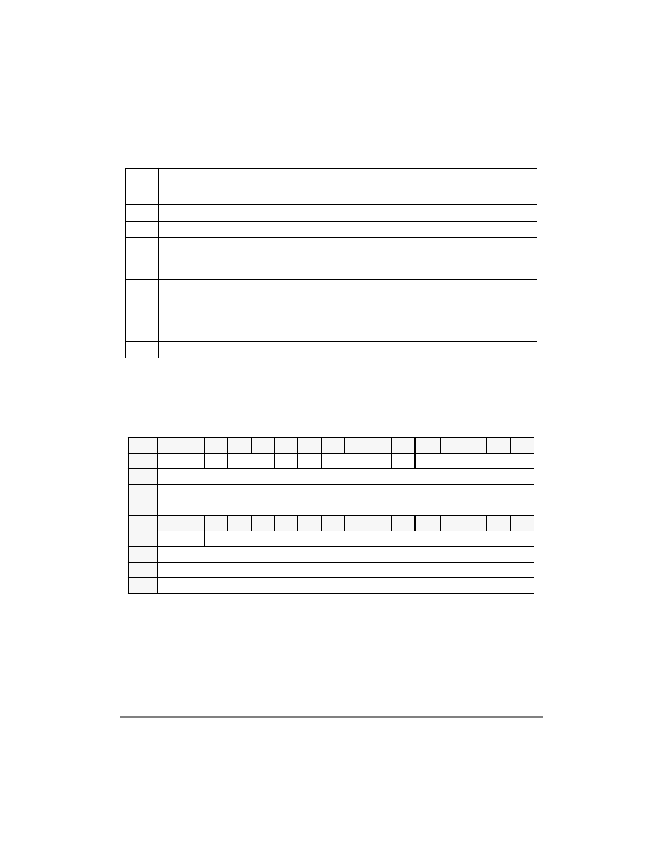
The TESCR2 register is described in Table 4-16.
4.3.2.12 Local Bus Transfer Error Status and Control Register 1
(L_TESCR1)
The local bus transfer error status and control register 1 (L_TESCR1) is shown in
Figure 4-33.
Table 4-16. TESCR2 Field Descriptions
Bits
Name
Description
0
Ñ
Reserved, should be cleared.
1
REGS
Internal registers error. An error occurred in a transaction to the MPC8260Õs internal registers.
2
DPR
Dual port ram error. An error occurred in a transaction to the MPC8260Õs dual-port RAM.
3Р6
С
Reserved, should be cleared.
7
LCL
Local bus bridge error. An error occurred in a transaction to the MPC8260Õs 60x bus to local bus
bridge.
8Ð15
PB
Parity error on byte. There are eight parity error status bits, one per 8-bit lane. A bit is set for the byte
that had a parity error.
16Ð27
BNK
Memory controller bank. There are twelve error status bits, one per memory controller bank. A bit is
set for the 60x bus memory controller bank that had an error. Note that this Þeld is invalid if the error
was not caused by ECC or parity checks.
28Р31
С
Reserved, should be cleared.
Bits
0
1
2
3
4
5
6
7
8
9
10
11
12
13
14
15
Field
BM
Ñ
PAR
Ñ
WP
Ñ
TC
Ñ
TT
Reset
0000_0000_0000_0000
R/W
R/W
Addr
Bits
16
17
18
19
20
21
22
23
24
25
26
27
28
29
30
31
Field
Ñ
DMD
Ñ
Reset
0000_0000_0000_0000
R/W
R/W
Addr
0x1004A
Figure 4-33. Local Bus Transfer Error Status and Control Register 1 (L_TESCR1)