Lcl_alrh -30, Lcl_acr field descriptions -30, Table 4-11 describes lcl_a cr register bits – Motorola MPC8260 User Manual
Page 168
4-30
MPC8260 PowerQUICC II UserÕs Manual
MOTOROLA
Part II. ConÞguration and Reset
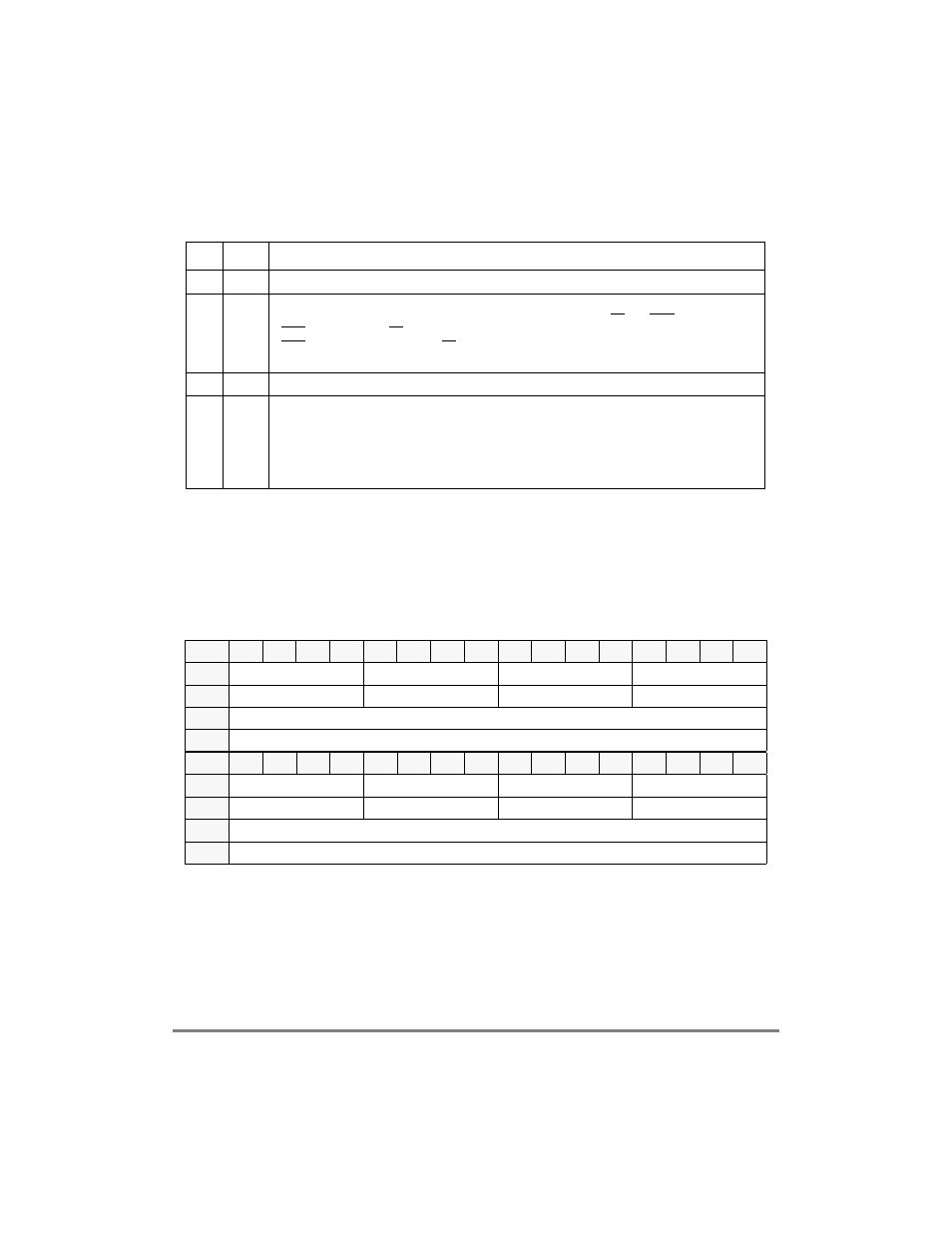
Table 4-11 describes LCL_ACR register bits.
4.3.2.5 Local Bus Arbitration Level Registers (LCL_ALRH and
LCL_ACRL)
The local bus arbitration level registers (LCL_ALRH and LCL_ALRL), shown in
Figure 4-26 and Figure 4-27, deÞnes arbitration priority for MPC8260 local bus masters 0Ð
7. Priority Þeld 0 has highest-priority. For information about the MPC8260 local bus master
indexes see LCL_ACR[PRKM] in Table 4-11.
LCL_ALRL, shown in Figure 4-27, deÞnes arbitration priority of MPC8260 local bus
masters 8Ð15.
Table 4-11. LCL_ACR Field Descriptions
Bits
Name
Description
0Р1
С
Reserved, should be cleared.
2
DBGD Data bus grant delay. SpeciÞes the minimum number of data tenure wait states for PowerPC
master-initiated data operations. This is the minimum delay between TS and DBG.
0 DBG is asserted with TS if the data bus is free.
1 DBG is asserted one cycle after TS if the data bus is not busy.
See Section 8.5.1, ÒData Bus Arbitration.У
3
С
Reserved, should be cleared.
4Ð7
PRKM Parking master. DeÞnes the parked master.
0000 CPM high request level
0001 CPM middle request level
0010 CPM low request level (default)
0011 Host bridge
Values 0100Ð1111 are reserved.
Bit
0
1
2
3
4
5
6
7
8
9
10
11
12
13
14
15
Field
Priority Field 0
Priority Field 1
Priority Field 2
Priority Field 3
Reset
0000
0001
0010
0011
R/W
R/W
Addr
Bit
16
17
18
19
20
21
22
23
24
25
26
27
28
29
30
31
Field
Priority Field 4
Priority Field 5
Priority Field 6
Priority Field 7
Reset
0100
0101
0110
0111
R/W
R/W
Addr
0x10040
Figure 4-26. LCL_ALRH