External rtd input connections -8, Can bus interface -8, Table 11-3. can bus interface terminals -8 – Basler Electric DGC-2020 User Manual
Page 406: Aem-2020, External rtd input connections, Can bus interface
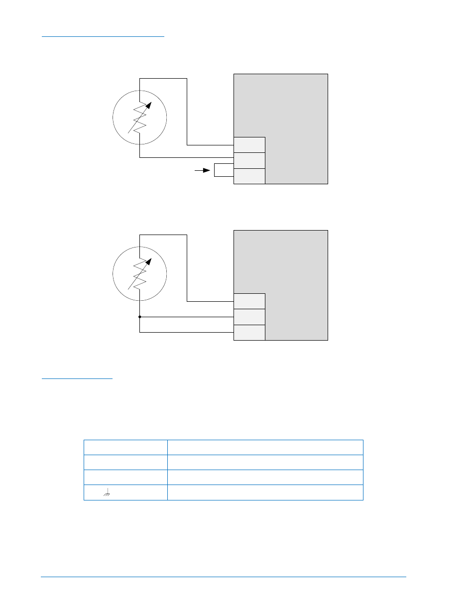
External RTD Input Connections
External 2-wire RTD input connections are shown in Figure 11-5. Figure 11-6 shows external 3-wire RTD
input connections.
Figure 11-5. External Two-Wire RTD Input Connections
Figure 11-6. External Three-Wire RTD Input Connections
CAN Bus Interface
These terminals provide communication using the SAE J1939 protocol and provide high-speed
communication between the Analog Expansion Module and the DGC-2020. Connections between the
AEM-2020 and DGC-2020 should be made with twisted-pair, shielded cable. CAN Bus interface terminals
are listed in Table 11-3. Refer to Figure 11-7 and Figure 11-8.
Table 11-3. CAN Bus Interface Terminals
Terminal
Description
P1- HI (CAN H)
CAN high connection (yellow wire)
P1- LO (CAN L)
CAN low connection (green wire)
P1-
(SHIELD)
CAN drain connection
RTD1+
RTD1–
RTD1C
AEM-2020
Jumper
P
0
0
5
3
-6
4
BLACK
RED
RTD1+
RTD1–
RTD1C
AEM-2020
P
0
0
5
3
-6
5
RED
BLACK
BLACK
11-8
DGC-2020 AEM-2020 (Analog Expansion Module)
9400200990 Rev X