Modem -10, Rdp-110 connections -10, O figure 6-7 – Basler Electric DGC-2020 User Manual
Page 276: Figure 6-8
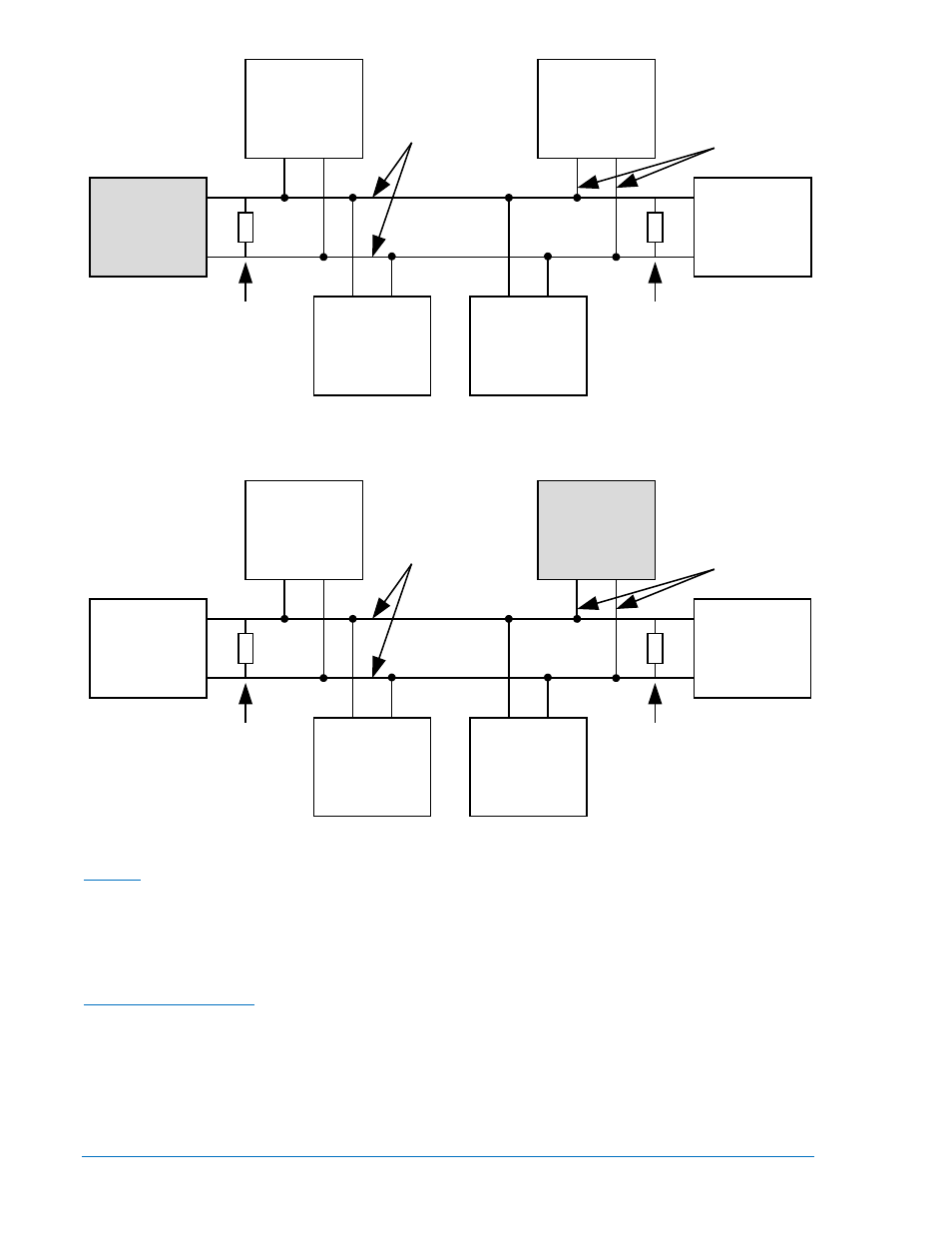
Figure 6-7. CAN Bus Interface with DGC-2020 providing One End of the Bus
Figure 6-8. CAN Bus Interface with Optional AEM-2020 providing One End of the Bus
Modem
DGC-2020 hardware version 3 controllers with style number xxxxxExxx are equipped with an RS-232
port. This port allows communication with an external, user-supplied modem with dial-in and dial-out
capability. DGC-2020 hardware versions 1 and 2 with style number xxxxxMxxx are equipped with an
internal modem with dial-in and dial-out capability. The modem connects to a standard-device telephone
line through a USOC RJ-11C jack.
RDP-110 Connections
Terminals are provided for connection with the optional RDP-110 remote display panel. These terminals
provide dc operating power to the RDP-110 and enable communication between the DGC-2020 and
RDP-110. Twisted-pair conductors are recommended for connecting the communication terminals of the
DGC-2020 and RDP-110. Communication may become unreliable if the connection wires exceed 4,000
feet.
Table 6-12 lists the DGC-2020 terminals that connect to the RDP-110.
AEM-2020
(Optional)
DGC-2020
Other
Devices
P0053-95
Engine
120 ohm
Termination
CAN-H
CAN-L
LSM-2020
(Optional)
CEM-2020
(Optional)
120 ohm
Termination
Bus
Stub
DGC-2020
AEM-2020
(Optional)
Other
Devices
P0053-94
Engine
120 ohm
Termination
CAN-H
CAN-L
LSM-2020
(Optional)
CEM-2020
(Optional)
120 ohm
Termination
Bus
Stub
6-10
DGC-2020 Installation
9400200990 Rev X