Multigen management, Avr output, Multigen management -86 – Basler Electric DGC-2020 User Manual
Page 196: Avr output -86, Figure 4-69. avr output -86
J
Speed Trim Enable: Enable or Disable.
K
Speed Trim Setpoint: Adjustable from 47 to 440 Hz in 0.01 Hz increments.
L
Trim Deadband: Adjustable from 0 to 2 percent in increments of 0.1
M
Remote Speed Bias: User Setting, LSM Analog Input 1, or ALG IN 1 through ALG IN 8.
N
Remote Speed Bias (%): Adjustable from 0 to 5%, in increments of 0.01.
O
Load Control Enabled: Enable or Disable.
P
Load Share Interface: Analog or Ethernet
Q
Proportional Gain (Kp): Adjustable from 0 to 1,000 in increments of 0.001.
R
Integral Gain (Ki): Adjustable from 0 to 1,000 in increments of 0.001.
S
Derivative Gain (Kd): Adjustable from 0 to 1,000 in increments of 0.001.
T
Derivative Filter Constant (Td): Adjustable from 0 to 1 in increments of 0.001.
U
Loop Gain (Kg): Adjustable from 1 to 1,000 in increments of 0.001.
V
Parallel To Mains Gain: Adjustable from 0 to 1,000 in increments of 0.001.
W
Droop Percentage: Adjustable from 0 to 10 percent in 0.001% increments.
X
Speed Droop Gain: Adjustable from 0 to 1,000 in increments of 0.001.
Y
Ramp Rate: Adjustable from 0 to 100 percent/second in 0.1%/s increments.
Z
Ramp Overshoot Reduction: Adjustable from 0 to 100% in increments of 1.
AA
Base Load Level Source: User Setting, LSM Analog Input 1, or Analog Inputs 1-8.
BB
Base Load Level: Adjustable from 0 to 100% in 1% increments.
CC
Baseload Analog Max: Adjustable from 0 to 100% in 0.1% increments.
DD
Baseload Analog Min: Adjustable from 0 to 100% in 0.1% increments.
EE
Breaker Open Setpoint: Adjustable from 0 to 100% in 0.1% increments.
Multigen Management
This group of settings is used when an optional LSM-2020 (Load Share Module) is connected to the
DGC-2020. Multigen management settings consist of settings for AVR output, governor output, load share
output, demand start/stop, generator sequencing, and network configuration.
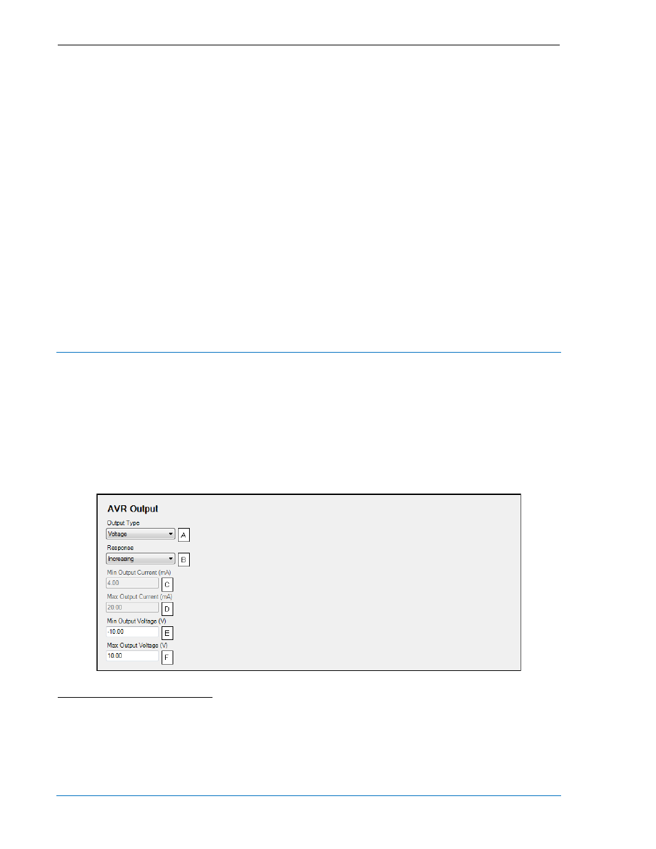
AVR Output
The AVR output
A
of the LSM-2020 is used to change the voltage setpoint of the generator. If the
response
B
is set for increasing, an increased bias will cause higher voltage. If the response
B
is set for
decreasing, an increased bias will cause lower voltage. Settings are provided for minimum output
current
C
, maximum output current
D
, minimum output voltage
E
, and maximum output voltage
F
.
The BESTCOMSPlus AVR Output screen is illustrated in Figure 4-69.
Figure 4-69. AVR Output
A
Output Type: Voltage or Current.
B
Response: Increasing or Decreasing.
C
Min Output Current: Adjustable from 4 to 20 mA in 0.1 mA increments.
D
Max Output Current: Adjustable from 4 to 20 mA in 0.1 mA increments.
E
Min Output Voltage: Adjustable from –10 to +10 V in 0.01 V increments.
F
Max Output Voltage: Adjustable from –10 to +10 V in 0.01 V increments.
4-86
DGC-2020 BESTCOMSPlus
® Software
9400200990 Rev X