Basler Electric DGC-2020 User Manual
Page 340
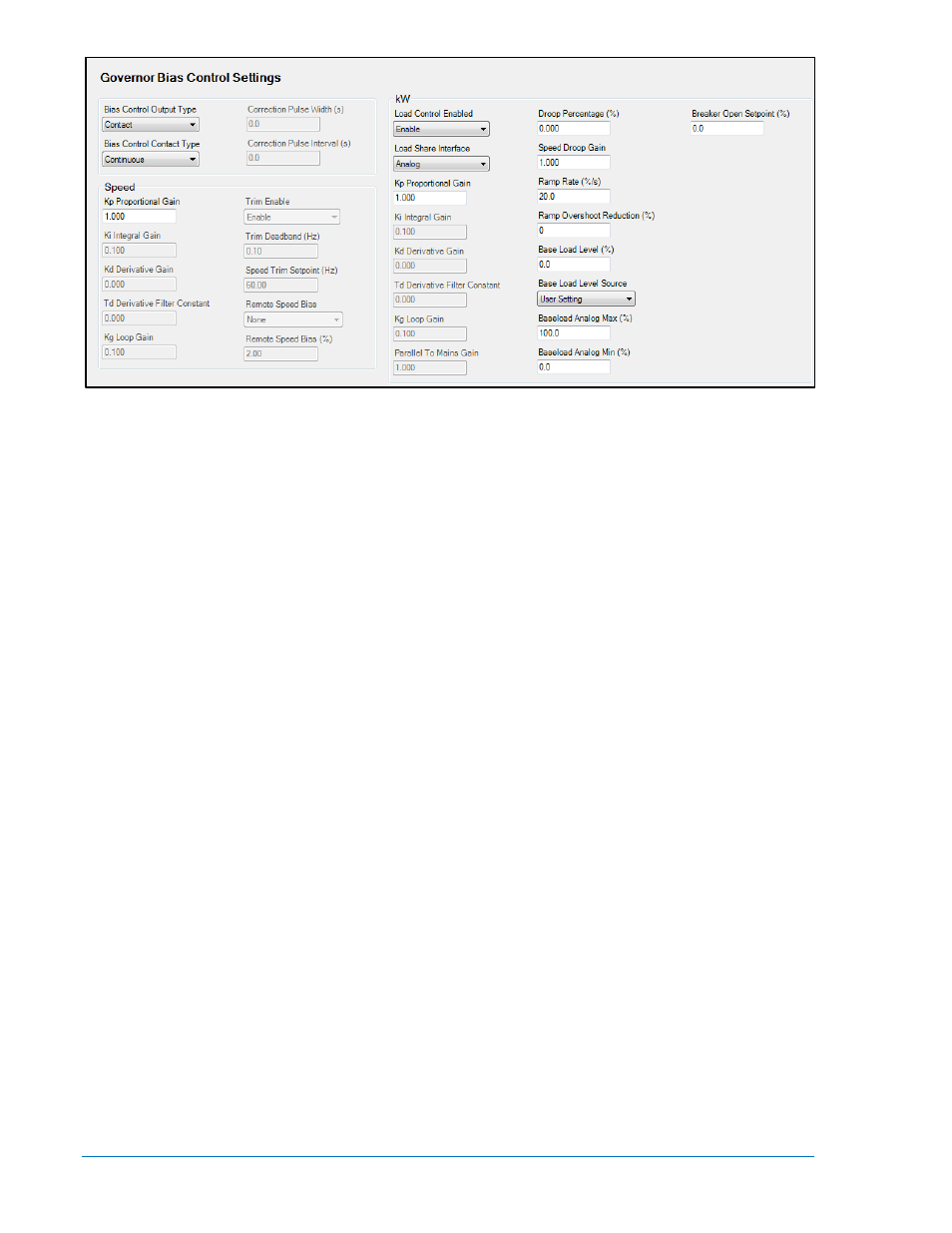
Figure 7-59. Settings Explorer, Bias Control Settings, Governor Bias Control Settings Screen
i. Bias Control Output Type - Select Contact or Analog, according to the machine’s
implementation.
ii. Bias Control Contact Type - Select Continuous or Proportional, depending on the
contact output type. Proportional is a PWM based implementation. The duty cycle
increases when more control output is required. This parameter cannot be
programmed if the Bias Control Output Type is set to Analog since it is not applicable
to analog outputs.
iii. Correction Pulse Interval - This parameter defines the duration in seconds between
output pulses for proportional contact outputs. This parameter cannot be
programmed if the Bias Control Output Type is set to Analog or the Bias Control
Contact Type is set to Continuous since it is not applicable in either case.
The pulse interval along with the pulse width specifies how often a new pulse occurs.
The total time between pulses is the pulse width plus the pulse interval.
iv. Correction Pulse Width - Set the maximum width of a contact output pulse for
proportional contact outputs. This is the maximum “On” time allowable for the
proportional outputs. This parameter cannot be programmed if the Bias Control
Output Type is set to Analog or the Bias Control Contact Type is set to Continuous
since it is not applicable in either case.
v. Speed Trim Enable - Speed trim maintains the system at the speed trim set point
when the generator breaker is closed and the generator is part of an islanded
system, i.e. not paralleled to the utility. This maintains the frequency of the island
system to compensate for speed deviations occurring from possible system “bumps”
as machines go on and off the bus. It is generally recommended that speed trim be
enabled. However, if an external speed POT is used for customer speed control, the
speed trim function will maintain the speed trim set point regardless of the POT
position. Effectively the speed POT is disabled.
The speed controller is active under two sets of circumstances: (1) the synchronizer
is active and biasing engine speed to accomplish alignment of the AC phases across
the breaker that is being synchronized or (2) the generator breaker is closed and
Speed Trim Enable is set to Enabled and the generator is NOT paralleled to the utility
as indicated by the parallel to mains (ParToMains) logic element in BESTlogicPlus
Programmable Logic.
vi. Speed Controller Gains (Kp, Ki, Kd, Td, Kg) - There are four Proportional - Integral -
Derivative (PID) controllers involved when a DGC-2020 and LSM-2020 are used in a
load sharing or load control system. The gains of the controllers involved with speed
control are discussed below. Controller gains are configured as part of the controller
tuning procedure. The tuning procedures for all PID controllers are presented in
Appendix C, Tuning PID Settings. Controller tuning is performed after all other
7-52
DGC-2020 Setup
9400200990 Rev X