Can bus interface -9, Table 9-4. can bus interface terminals -9 – Basler Electric DGC-2020 User Manual
Page 379
Terminal
Description
P2-5 (LS–)
Load share line negative
P2-4 (LS’)
Provides additional landing point for external resistor
CAN bus Interface
These terminals provide communication using the SAE J1939 protocol and provide high-speed
communication between the LSM-2020 and the DGC-2020. Connections between the LSM-2020 and
DGC-2020 should be made with twisted-pair, shielded cable. CAN bus interface terminals are listed in
Table 9-4. Refer to Figure 9-6 and Figure 9-7.
Table 9-4. CAN bus Interface Terminals
Terminal
Description
P2-12 (CAN L)
CAN low connection (green wire)
P2-11 (CAN H)
CAN high connection (yellow wire)
P2-10 (SHIELD)
CAN drain connection
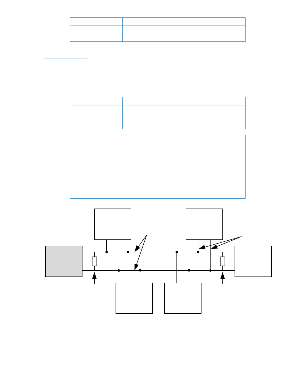
NOTES
1. If the LSM-2020 is providing one end of the J1939 bus, a 120
Ω, ½ watt
terminating resistor should be installed across terminals P2-12 (CANL)
and P2-11 (CANH).
2. If the LSM-2020 is not part of the J1939 bus, the stub connecting the LSM-
2020 to the bus should not exceed 914 mm (3 ft) in length.
3. The maximum bus length, not including stubs, is 40 m (131 ft).
4. The J1939 drain (shield) should be grounded at one point only. If
grounded elsewhere, do not connect the drain to the LSM-2020.
Figure 9-6. CAN bus Interface with LSM-2020 providing One End of the Bus
AEM-2020
(Optional)
LSM-2020
Other
Devices
P0053-58
Engine
120 ohm
Termination
CAN-H
CAN-L
CEM-2020
(Optional)
DGC-2020
120 ohm
Termination
Bus
Stub
9400200990 Rev X
DGC-2020 LSM-2020 (Load Share Module)
9-9