Basler Electric DGC-2020 User Manual
Page 308
b. Alarm Configuration - Select None, Alarm, or Pre-Alarm for the desired behavior of this
function. Regardless of the selection, the indicator on the RDP-110 will illuminate if an input
has been assigned and the input is on.
c. Activation Delay - Set the delay for which the input must be true before the alarm or pre-
alarm will be annunciated. This can be used to prevent “glitches” on the input from causing
spurious annunciation.
8. Low Coolant Level
a. Input - Select an input for this function to indicate a low coolant level. When this input is true,
an alarm or pre-alarm is annunciated based on the alarm configuration, and the Low Coolant
Level indicator on the RDP-110 (Remote Display Panel) will illuminate. Select None to
disable the programmable function.
b. Alarm Configuration - Select None, Alarm, or Pre-Alarm for the desired behavior of this
function. Regardless of the selection, the indicator on the RDP-110 will illuminate if an input
has been assigned and the input is on.
c. Activation Delay - Set the delay for which the input must remain true before the alarm or pre-
alarm is annunciated. This can be used to prevent “glitches” on the input from causing
spurious annunciation.
9. Fuel Leak Detect
a. Input - Select an input for this function to indicate when a fuel leakage condition has been
detected. When this input is true, an alarm or pre-alarm is announced based on the alarm
configuration and the Fuel Leak indicator on the RDP-110 (Remote Display Panel) will
illuminate. Select None to disable the programmable function.
b. Alarm Configuration - Select None, Alarm, or Pre-Alarm for the desired behavior of this
function. Regardless of the selection, the indicator on the RDP-110 will illuminate if an input
has been assigned and the input is on.
c. Activation Delay - Set the delay for which the input must remain true before the alarm or pre-
alarm will be annunciated. This can be used to prevent “glitches” on the input from causing
spurious annunciation.
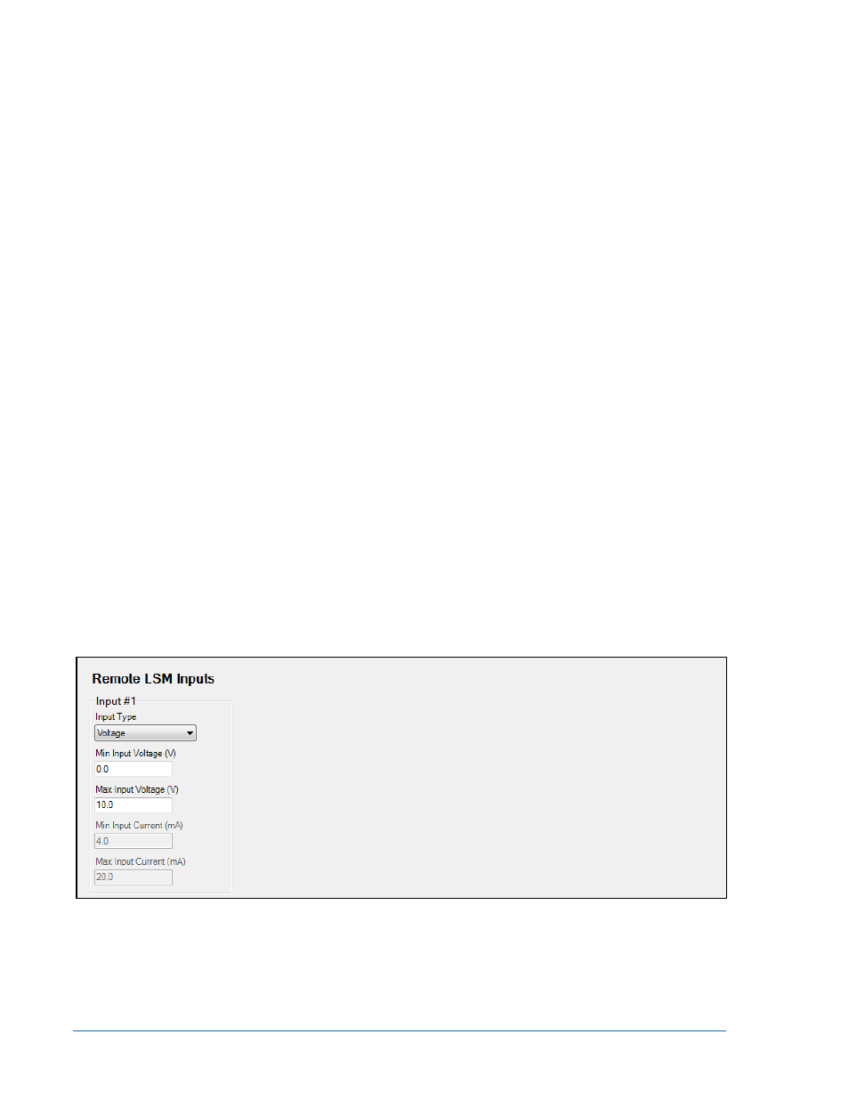
Configuring Remote LSM Inputs on the LSM-2020 (Load Share Module)
Front Panel Navigation Path: SETTINGS > PROGRAMMABLE INPUTS > LSM INPUTS
The LSM-2020 has one analog input. It is reserved for use with kW and/or kvar control and can be used
as a source for the kW Base Load (%) setting, the kvar Setpoint (%) setting, or the PF Setpoint setting.
However, the input type (4-20 mA or 0-10 Vdc) and the input range must be set on the Remote LSM
Inputs screen in BESTCOMSPlus
®. See Figure 7-24.
Figure 7-24. Settings Explorer, Programmable Inputs, Remote LSM Inputs Screen
The parameters to be configured are:
1. Input Type - Select Voltage for a 0-10 Vdc input or Current for a 4-20 mA current input.
2. Min Input Voltage (V) - This setting defines the minimum valid voltage expected from the transducer
or device connected to the analog input. Voltage below this threshold will be limited to this value. The
Min Input Voltage setting can be set only when Voltage is selected as the Input Type.
7-20
DGC-2020 Setup
9400200990 Rev X