Basler Electric DGC-2020 User Manual
Page 256
Name
Description
Symbol
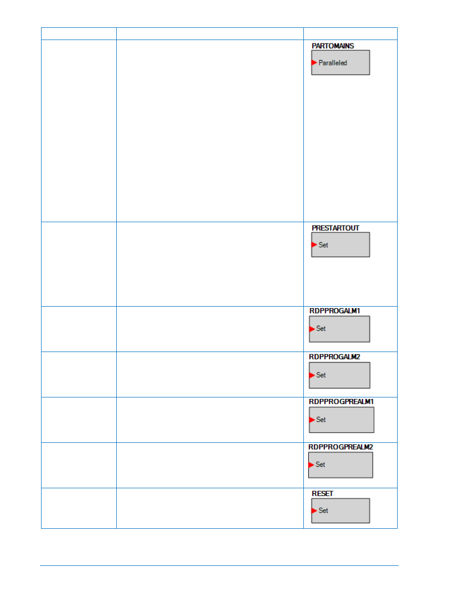
PARTOMAINS
Setting this logic element to true indicates to the DGC-
2020 that it is paralleled to a utility.
When paralleled to the utility, the kW controller will
regulate the machine’s kW output at the Base Load Level
(%) that is set on the Governor Bias Control Settings
screen, where the Base Load Level is in percent of
machines rated kW. Otherwise, the kW controller will
implement kW load sharing when part of a load sharing
system. If a load sharing system is not implemented, the
speed controller can be set up to implement speed droop.
When paralleled to the utility, the var/PF controller will
regulate the machine’s reactive power output according to
the control mode setting. If the control mode is var
Controller, the output will be regulated to the kvar Setpoint
(%) that is set on the AVR Bias Control Settings screen,
where the kvar Setpoint (%) is in percentage of the
machines rated kvar. If the control mode is PF Control, the
reactive power output is regulated to a level that maintains
the machines power factor at the value specified by the PF
setting on the AVR Bias Control Settings screen. When
var/PF control is not active or not enabled, the voltage
controller can be set up to implement voltage droop.
PRESTARTOUT
This element is used to drive the prestart output relay from
logic when the Prestart Output Relay configuration is set to
“Programmable”. When the Prestart Output Relay
configuration is set to “Programmable”, the prestart relay
will not close unless logic is used to drive this element.
When the Prestart Output Relay configuration is set to
“Predefined”, the prestart relay is closed according to the
predefined prestart functionality of the DGC-2020. When
the “Predefined” functionality is selected, the relay will not
respond to this element.
RDPPROGALM1
When true, this element illuminates the Fuel Leak/Sender
Failure LED on the Remote Display Panel RDP-110. When
this element is connected in logic, it overrides all other
commands to the LED. Otherwise, the LED operates as
normal.
RDPPROGALM2
When true, this element illuminates the Sender Failure
LED on the Remote Display Panel RDP-110.
When this
element is connected in logic, it overrides all other
commands to the LED. Otherwise, the LED operates as
normal.
RDPPROGPREALM1 When true, this element illuminates the Battery
Overvoltage LED on the Remote Display Panel RDP-110.
When this element is connected in logic, it overrides all
other commands to the LED. Otherwise, the LED operates
as normal.
RDPPROGPREALM2 When true, this element illuminates the Battery Charger
Failure LED on the Remote Display Panel RDP-110.
When this element is connected in logic, it overrides all
other commands to the LED. Otherwise, the LED operates
as normal.
RESET
Reset will be active when this element is true. Reset can
also be accomplished by pressing the Reset button on the
front panel of the DGC-2020.
5-28
DGC-2020 BESTlogic
™
Plus Programmable Logic
9400200990 Rev X