Remote module setup, Remote module setup -34, Figure 4-27. remote module setup -34 – Basler Electric DGC-2020 User Manual
Page 144: Load sharing module, Contact expansion module, Analog expansion module
G
Alternate Frequency: Adjustable from 10 to 450 Hz in 0.01 Hz increments.
H
Rated Power Factor: Adjustable from –1 to +1 in increments of 0.0001.
I
Speed Signal Source: MPU, Gen Freq, or MPU Freq.
J
Rated Frequency: 50/60 or 400 Hz.
K
Rated Engine RPM: Adjustable from 750 to 3,600 in increments of 1.
L
Number Fly Wheel Teeth: Adjustable from 1 to 500 in increments of 0.1.
M
EPS Current Threshold: Adjustable from 3 to 10% of the CT primary rating in 1% increments.
N
Low Line Scale Factor: Adjustable from 0.001 to 3 in increments of 0.001.
O
System Units: English or Metric.
P
Metric Pressure Units: Bar or kPa/MPa.
Q
Battery Volts: 12 or 24 Vdc.
R
NFPA Level: 0 disables NFPA compliance, 1 enables Level 1 NFPA compliance, 2 enables Level 2.
S
Fuel Level Function: Disable, Fuel Lvl, Natural Gas, or Liquid Propane.
T
Source: Sender or ALG IN 1 through ALG IN 8.
U
Maximum Percent: Adjustable from 0 to 200% in 1% increments.
V
Minimum Percent: Adjustable from 0 to 200% in 1% increments.
W
Power Up Delay: Adjustable from 0 to 60 s in 1 s increments.
X
Generator Frequency: 50/60 Hz or 400 Hz.
Y
Calculated Values.
Z
Rated Volts (Low Line Scale Factor): Adjustable from 0.001 to 3.000 in increments of 0.001.
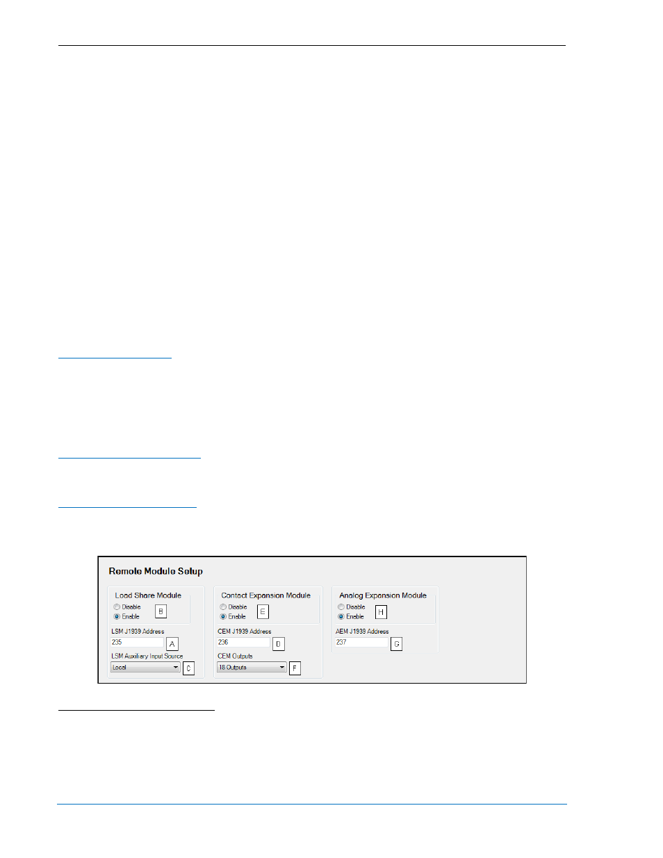
Remote Module Setup
The following settings are used to configure the LSM-2020, CEM-2020, and AEM-2020.
Load Sharing Module
A J1939 Address
A
must be entered when an optional LSM-2020 is enabled
B
. Use the LSM Auxiliary Input
Source setting
C
to select the source of the input values used for controlling the DGC-2020. If Local is
selected, the LSM-2020 uses its locally measured input values. If System Manager is selected, the LSM-
2020 uses the input values received through inter-genset communications from the unit designated as the
system manager. Note that the unit in the system with the lowest nonzero sequencing ID is the system
manager.
Contact Expansion Module
A J1939 Address
D
must be entered when the optional CEM-2020 is enabled
E
. Select number of CEM-
2020 outputs
F
.
Analog Expansion Module
A J1939 Address
G
must be entered when the optional AEM-2020 is enabled
H
.
The BESTCOMSPlus Remote Module Setup screen is illustrated in Figure 4-27.
Figure 4-27. Remote Module Setup
A
LSM J1939 Address: Adjustable from 1 to 253 in increments of 1.
B
Load Share Module: Enable or Disable.
C
LSM Auxiliary Input Source: Local or System Manager
D
CEM J1939 Address: Adjustable from 1 to 253 in increments of 1.
E
Contact Expansion Module: Enable or Disable.
F
CEM Outputs: 18 Outputs or 24 Outputs.
G
AEM J1939 Address: Adjustable from 1 to 253 in increments of 1.
4-34
DGC-2020 BESTCOMSPlus
® Software
9400200990 Rev X