Maintenance, Maintenance -9 – Basler Electric DGC-2020 User Manual
Page 395
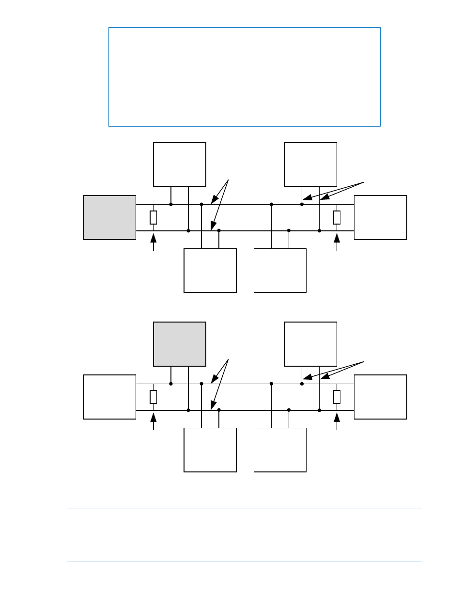
NOTES
1. If the CEM-2020 is providing one end of the J1939 bus, a 120
Ω, ½ watt
terminating resistor should be installed across terminals P1- LO (CANL)
and P1- HI (CANH).
2. If the CEM-2020 is not part of the J1939 bus, the stub connecting the
CEM-2020 to the bus should not exceed 914 mm (3 ft) in length.
3. The maximum bus length, not including stubs, is 40 m (131 ft).
4. The J1939 drain (shield) should be grounded at one point only. If
grounded elsewhere, do not connect the drain to the CEM-2020.
Figure 10-5. CAN Bus Interface with CEM-2020 providing One End of the Bus
Figure 10-6. CAN Bus Interface with DGC-2020 providing One End of the Bus
Maintenance
Preventive maintenance consists of periodically checking that the connections between the CEM-2020
and the system are clean and tight. Contact Expansion Modules are manufactured using state-of-the-art
surface-mount technology. As such, Basler Electric recommends that no repair procedures be attempted
by anyone other than Basler Electric personnel.
AEM-2020
(Optional)
CEM-2020
Other
Devices
P0053-60
Engine
120 ohm
Termination
CAN-H
CAN-L
LSM-2020
(Optional)
DGC-2020
120 ohm
Termination
Bus
Stub
AEM-2020
(Optional)
DGC-2020
Other
Devices
P0053-61
Engine
120 ohm
Termination
CAN-H
CAN-L
LSM-2020
(Optional)
CEM-2020
120 ohm
Termination
Bus
Stub
9400200990 Rev X
DGC-2020 CEM-2020 (Contact Expansion Module)
10-9