Rs-485 communication port -9, Can bus interface -9, Table 6-10. rs-485 communication port terminals -9 – Basler Electric DGC-2020 User Manual
Page 275: Table 6-11. can bus interface terminals -9
RS-485 Communication Port
DGC-2020 controllers with the optional RS-485 communication port (style number xxxRxxxxx) are
equipped for polled communication over a Modbus
™ network. Twisted-pair, shielded cable is
recommended for RS-485 port connections. RS-485 communication port terminals are listed in Table
6-10.
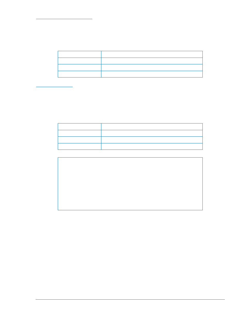
Table 6-10. RS-485 Communication Port Terminals
Terminal
Description
12 (485 SHIELD)
Shield connection for RS-485 cable
13 (485B)
RS-485 send/receive B connection
14 (485A)
RS-485 send/receive A connection
CAN Bus Interface
These terminals provide communication using the SAE J1939 protocol or the MTU protocol and provide
high-speed communication between the DGC-2020 and an MTU engine ECU on an electronically
controlled engine. Connections between the MTU engine ECU and DGC-2020 should be made with
twisted-pair, shielded cable. CAN bus interface terminals are listed in Table 6-11. Refer to Figure 6-7 and
Figure 6-8.
Table 6-11. CAN Bus Interface Terminals
Terminal
Description
48 (CAN L)
CAN low connection
49 (CAN H)
CAN high connection
50 (SHIELD)
CAN drain connection
NOTES
1. If the DGC-2020 is providing one end of the J1939 bus, a 120
Ω, ½ watt
terminating resistor should be installed across terminals 48 (CANL) and 49
(CANH).
2. If the DGC-2020 is not part of the J1939 bus, the stub connecting the
DGC-2020 to the bus should not exceed 914 mm (3 ft) in length.
3. The maximum bus length, not including stubs, is 40 m (131 ft).
4. The J1939 drain (shield) should be grounded at one point only. If
grounded elsewhere, do not connect the drain to the DGC-2020.
9400200990 Rev X
DGC-2020 Installation
6-9