Bestlogic™plus examples, Example 1 - avr logic block connections, Example 2 - and gate connections – Basler Electric DGC-2020 User Manual
Page 262: Example 3 - multiple logic connections, Downloading a bestlogic, Plus file -34, Printing a bestlogic, Clearing the on-screen logic diagram -34, Bestlogic, Plus examples -34
Downloading a BESTlogic
™
Plus File
To download a BESTlogicPlus file from the DGC-2020, you must pull down the Communication menu and
select Download Logic. If the logic in your BESTCOMSPlus has changed, a dialog box will open asking
you if want to save the current logic changes. You may choose Yes or No. After you have taken the
required action to save or not save the current logic, the downloading is executed.
Printing a BESTlogic
™
Plus File
To view a preview of the printout, click on the Print Preview icon located on the BESTlogicPlus
Programmable Logic toolbar. If you wish to print to a printer, select the printer icon in the upper left corner
of the Print Preview screen.
You may skip the print preview and go directly to print by clicking on the Printer icon on the
BESTlogicPlus Programmable Logic toolbar. A dialog box, Select Views to Print opens allowing you to
check which views you would like to print. Next, the Print dialog box opens with the typical Windows
choice to setup the properties of printer. Execute this command, as necessary, and then select Print.
A Page Setup icon is also provided on the BESTlogicPlus Programmable Logic toolbar allowing you to
select Paper Size, Paper Source, Orientation, and Margins.
Clearing the On-Screen Logic Diagram
Click on the Clear button to clear the on-screen logic diagram and start over.
BESTlogic
™
Plus Examples
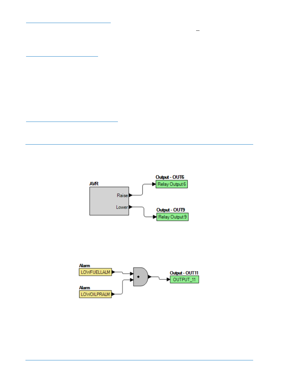
Example 1 - AVR Logic Block Connections
Figure 5-5 illustrates the AVR logic block and two output logic blocks. Output 6 is active while the AVR is
being raised and Output 9 is active while the AVR is being lowered.
Figure 5-5. Example 1 - AVR Logic Block Connections
Example 2 - AND Gate Connections
Figure 5-6 illustrates a typical AND gate connection. In this example, Output 11 will become active when
the Low Fuel alarm AND the Low Oil Pressure alarm are true.
Figure 5-6. Example 2 - AND Gate Connections
Example 3 - Multiple Logic Connections
In this example, there are two comment boxes, which may be placed on the logic diagram. Double-click a
comment box to modify the inside text. Output 5 will become true when the 27TRIP is TRUE. Output 7 will
become true when the Cool Temp Sender Fail is true. Output 1 will become true when the DGC-2020 is in
RUN mode (RUN Mode true). Refer to Figure 5-7.
5-34
DGC-2020 BESTlogic
™
Plus Programmable Logic
9400200990 Rev X