Figure 4-68. governor bias control settings -85 – Basler Electric DGC-2020 User Manual
Page 195
desired droop performance. In order to test the operation of droop, the unit must be loaded to full load
and the resulting generator speed should be compared to the desired droop. If it is not possible to load
the unit to full load, the droop test can be performed at partial load. The expected speed is determined by
the following equation.
Expected rpm reduction in droop - (actual load/machine capacity)
∗ (droop percentage/100) ∗ rated
speed.
If the actual rpm drop does not match the expected value, calculate the error by dividing the expected
drop by the actual drop, and putting the result in as the droop gain.
Ramp rate
Y
is defined as the rate, in percentage of machine capacity, at which the machine will ramp up
its real power when loading or coming online. The machine also uses this rate to unload prior to cooling
down. If a machine is the only machine online, ramping will not be in effect.
After ramping a generator's kW output, to bring it online or offline, overshoot may occur. The likeliness of
kW overshoot increases as the ramp rate increases. Typically, overshoot is reduced by lowering the ramp
rate to the slowest possible setting. If overshoot is still a problem, the Ramp Overshoot Reduction
Z
setting
can be used. A setting of 0% overshoot reduction results in no change to the amount of overshoot. A
setting of 100% provides maximum overshoot reduction. Ramp Overshoot Reduction must be tuned to
the optimal level. Too little reduction may result in overshoot while too much reduction may result in
undershoot.
When User Setting is selected for the base load level source
AA
, the base load level setting
BB
determines
the percent of machine capacity at which the kW controller will regulate if the generator is paralleled to the
utility. If paralleled to the utility, the Parallel to Mains logic element in BESTlogicPlus must be driven by
logic or a contact input. If parallel to utility operation is undertaken and the Parallel to Mains logic element
is not implemented, the DGC-2020 will remain in kW load share and will either move toward operation at
100% of capacity or 0 capacity resulting in damage to the machine or system.
When the base load level source is configured for LSM-2020 input or an AEM-2020 input, the operating
kW controller set point is calculated based on the specific analog input. Parameters are available for
baseload analog max
CC
and baseload analog min
DD
.
When the unit unloads, the generator breaker will open when the power generated by the unit falls below
the breaker open setpoint
EE
.
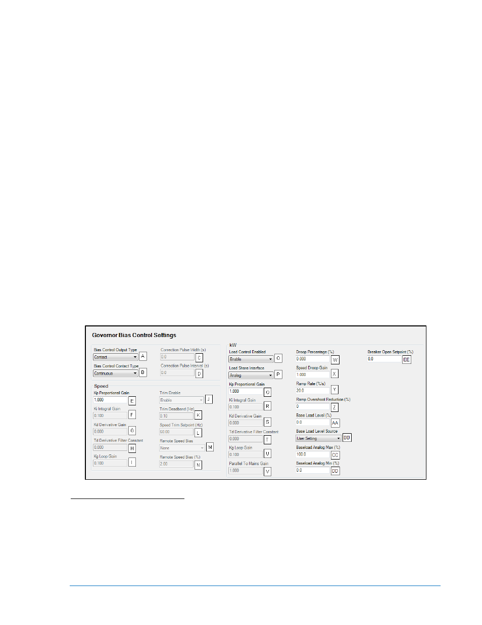
Figure 4-68. Governor Bias Control Settings
A
Bias Control Output Type: Contact or Analog.
B
Bias Control Contact Type: Continuous or Proportional.
C
Correction Pulse Width: Adjustable from 0 to 99.9 s in 0.1 s increments.
D
Correction Pulse Interval: Adjustable from 0 to 99.9 s in 0.1 s increments.
E
Proportional Gain (Kp): Adjustable from 0 to 1,000 in increments of 0.001.
F
Integral Gain (Ki): Adjustable from 0 to 1,000 in increments of 0.001.
G
Derivative Gain (Kd): Adjustable from 0 to 1,000 in increments of 0.001.
H
Derivative Filter Constant (Td): Adjustable from 0 to 1 in increments of 0.001.
I
Loop Gain (Kg): Adjustable from 0 to 1,000 in increments of 0.001.
9400200990 Rev X
DGC-2020 BESTCOMSPlus
® Software
4-85