Mounting, Connections, Mounting -4 – Basler Electric DGC-2020 User Manual
Page 402: Connections -4, Terminations -4, Figure 11-1. aem-2020 overall dimensions -4
Mounting
Analog Expansion Modules are contained in a potted plastic case and may be mounted in any convenient
position. The construction of an Analog Expansion Module is durable enough to mount directly on a
genset using ¼-inch hardware. Hardware selection should be based on any expected
shipping/transportation and operating conditions. The torque applied to the mounting hardware should not
exceed 65 in-lb (7.34 N•m).
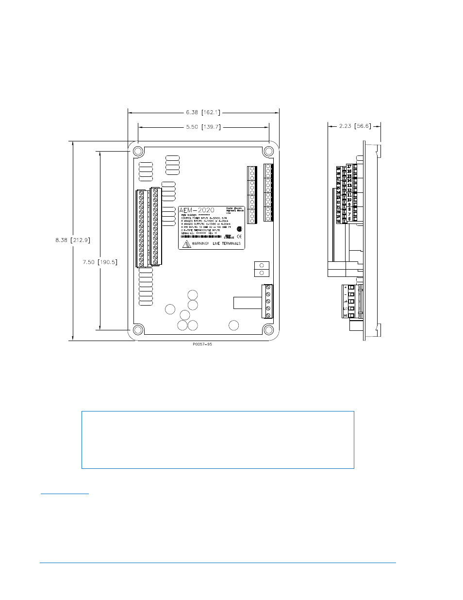
See Figure 11-1 for AEM-2020 overall dimensions. All dimensions are shown in inches with millimeters in
parenthesis.
Figure 11-1. AEM-2020 Overall Dimensions
Connections
Analog Expansion Module connections are dependent on the application. Incorrect wiring may result in
damage to the module.
NOTES
Operating power from the battery must be of the correct polarity. Although
reverse polarity will not cause damage, the AEM-2020 will not operate.
Be sure that the AEM-2020 is hard-wired to earth ground with no smaller than
12 AWG copper wire attached to the chassis ground terminal on the module.
Terminations
The terminal interface consists of both plug-in connectors and a permanently mounted connector with
screw-down compression terminals.
AEM-2020 connections are made with one 5-position connector, two 12-position connectors, two 16-
position connectors, and two 2-position thermocouple connectors. The 16, 5, and 2-position connectors
plug into headers on the AEM-2020. The connectors and headers have dovetailed edges that ensure
proper connector orientation. Also, the connectors and headers are uniquely keyed to ensure that the
11-4
DGC-2020 AEM-2020 (Analog Expansion Module)
9400200990 Rev X