Step by step setup procedures -49 – Basler Electric DGC-2020 User Manual
Page 337
Step by Step Setup Procedures
1. Wire the DGC-2020, LSM-2020, and any external devices that interact with the DGC-2020 or the
LSM-2020. Descriptions of DGC-2020 connections and diagrams showing typical wiring schemes for
a DGC-2020 on a generator in various connection schemes (single-phase AB, single-phase AC, Wye,
Delta, etc.) are found under Connections.
Descriptions of the LSM-2020 connections and diagrams showing typical wiring schemes for
connecting DGC-2020s and LSM-2020s on several machines which parallel together to form a load
sharing system are found under Installation in Section 9, LSM-2020 (Load Share Module).
2. Set all DGC-2020 settings related to Initial Machine Setup. Initial machine setup should be performed
according to the paragraphs titled DGC-2020 Initial Setup.
3. Configure DGC-2020 breaker control. If the DGC-2020 is controlling the generator breaker in the
system, it should be configured according to the paragraphs titled Generator and Mains Breaker
Control. If the breaker is controlled by external switchgear, most of this may be omitted. However, it is
still necessary to implement a contact input to the generator breaker block in the DGC-2020
BESTlogicPlus Programmable Logic to indicate generator breaker status to the DGC-2020. The
DGC-2020 will not load share or control kW or kvar unless it receives an indication that the generator
breaker is closed.
4. Configure the synchronizer function. If the synchronizer option in the DGC-2020 is used to
synchronize the DGC-2020 to the generator bus or to the utility, it should be configured according to
the paragraphs titled Synchronizer Setup. If an external synchronizer is used for synchronization and
the DGC-2020 load sharing is also configured, special wiring consideration is required to prevent both
the LSM-2020 and the external synchronizer from trying to drive the AVR bias and the Governor bias
at the same time. Examples of such wiring schemes are presented in the paragraphs titled Interfacing
an External Control Device with a DGC-2020
− LSM-2020 System under Application in Section 9,
LSM-2020 (Load Share Module).
5. Configure the parameters related to load sharing and kW control.
a. Enable the load share module. The load share module setup is found in BESTCOMSPlus
®
under SETTINGS EXPLORER
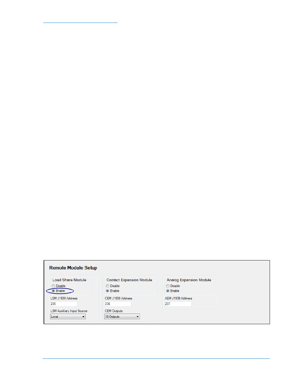
DGC-2020 SYSTEM SETTINGS REMOTE MODULE
SETUP. See Figure 7-55.
Front Panel Navigation Path: SETTINGS > SYSTEM PARAMS > REMOTE MODULE
SETUP
i. Enable the load share module by clicking Enable under the load share module
settings.
ii. LSM J1939 Address - Enter the J1939 address to be used by the LSM-2020.
Normally this will not have to be changed unless the address is already in use
elsewhere on the CAN bus network.
iii. LSM Auxiliary Input Source - Select Local if locally measured input values are to be
used. Select System Manager if the measured input values of the unit designated as
the system manager are to be used.
Figure 7-55. Settings Explorer, System Parameters, Remote Module Setup Screen
b. Configure the load share line voltage range. If load sharing to equipment not produced by
Basler Electric, the range of load share voltage utilized by the equipment must be
determined. If the voltage range set up in the DGC-2020 does not match that of the devices,
correct load sharing will not occur. If all devices are Basler Electric devices, a range of 0 to 10
9400200990 Rev X
DGC-2020 Setup
7-49