Speed setup, Voltage regulator setup, Speed setup -27 – Basler Electric DGC-2020 User Manual
Page 137: Voltage regulator setup -27, Figure 4-21. speed setup -27
V
Mode Switch: Off or On.
W
Governor Param Set Select: Adjustable from 0 to 1,000 in increments of 1.
X
CAN Rating Switch 1 & 2: Off or On.
Y
Cylinder Cutout Disable 1 & 2: Off or On.
Z
MTU ECU7/ECU8 Module Type: 501 or 502.
AA
Engine Operating Mode: 1 or 2.
BB
Regeneration Interlock: Enable or Disable.
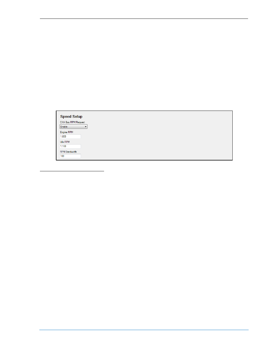
Speed Setup
Speed control and kW load sharing over J1939 and ECU7/ECU8 is implemented over CAN bus when the
CAN Bus rpm Request
A
setting is enabled. This is implemented for all ECUs. The Engine rpm
B
setting
defines the nominal requested engine rpm. The Idle rpm
C
setting is the requested rpm when the IDLE
REQUEST logic element is true. The rpm Bandwidth
D
setting defines the range of rpm in which the DGC-
2020 will use to accomplish load sharing. For example, if the Engine rpm setting is 1800 and the RPM
Bandwidth is set to 100, the rpm request can go from 1750 to 1850 rpm when load sharing is in effect.
Figure 4-21. Speed Setup
A
CAN bus rpm Request: Enable or Disable.
B
Engine rpm: Adjustable from 1,400 to 2,000 in increments of 1.
C
Idle rpm: Adjustable from 100 to 2,000 in increments of 1.
D
RPM Bandwidth: Adjustable from 0 to 1,000 in increments of 1.
Voltage Regulator Setup
The DGC-2020 transmits voltage setpoint and underfrequency compensation parameters to Marathon
DVR2000E+ voltage regulators. The Voltage Regulator Setup screen (Figure 4-22) is found in the
BESTCOMSPlus
®
Settings Explorer under the Communications, CANBus category. The CAN Bus Type
setting
A
allows the user to select which CAN Bus type is used to transmit parameters to the voltage
regulator. The Primary Voltage Setpoint
B
value represents the normal desired system voltage setpoint.
Alternate Voltage Setpoint
C
is the desired system voltage setpoint when low line override is true. The
range in which the DGC-2020 is allowed to bias voltage regulator var sharing and voltage trim is
adjustable using the Voltage Adjust Bandwidth
D
setting. When the DVR2000E+ is in Field Current
Regulation (FCR) mode, the normal desired field current setpoint is adjusted using the Field Current
Setting
E
. The Primary Underfrequency Knee
F
setting allows adjustment of the normal desired
underfrequency knee-point. When low line override is true, the Alternate Underfrequency Knee
G
becomes
the active underfrequency knee-point. The desired Underfrequency Slope
H
can also be specified.
9400200990 Rev X
DGC-2020 BESTCOMSPlus
® Software
4-27