Basler Electric DGC-2020 User Manual
Page 325
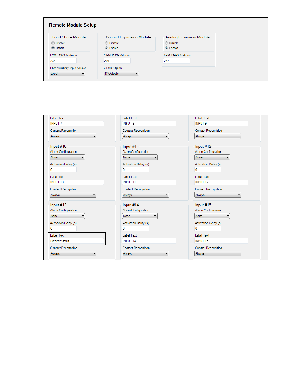
Figure 7-40. Settings Explorer, System Parameters, Remote Module Setup Screen
3. Next, click Programmable Inputs, then Contact Inputs to label the Breaker Status input (Input 13 is
the default). See Figure 7-41.
Front Panel Navigation Path: SETTINGS > PROGRAMMABLE INPUTS > CONFIGURABLE INPUTS
Figure 7-41. Settings Explorer, Programmable Inputs, Contact Inputs Screen
4. Click on Programmable Outputs then Contact Outputs. Select and label the appropriate outputs for
Breaker Close (Output 5 is the default) and Breaker Open (Output 6 is the default). If using contact
outputs on the DGC-2020 for Governor and Voltage Regulator control, the contact outputs can be
labeled here as well. Default logic is Output 9 =GOV Raise, Output 10 = GOV Lower, Output 11 =
AVR Raise, and Output 12 = AVR Lower. See Figure 7-42.
Front Panel Navigation Path: SETTINGS > PROGRAMMABLE OUTPUTS > OUTPUTS
9400200990 Rev X
DGC-2020 Setup
7-37