Figure 6-4. interposing relay diagram -6, Dgc-2020 – Basler Electric DGC-2020 User Manual
Page 272
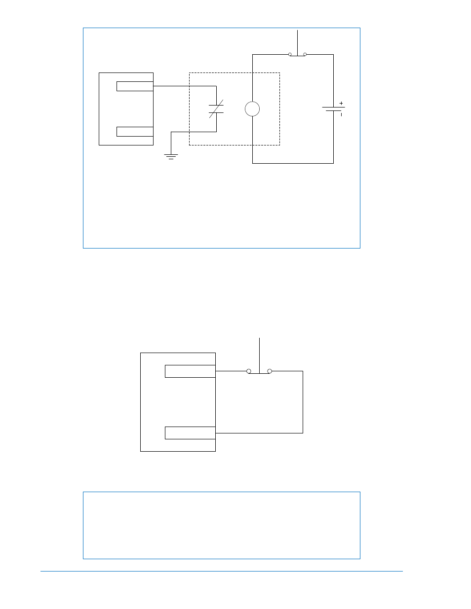
Figure 6-4. Interposing Relay Diagram
The relay is the type that when the coil is NOT energized, the contacts are
open. When the coil is energized, the relay contacts are closed. The ESTOP
button is normally closed (i.e. closed when it is NOT pushed). The relay coil is
always energized when the ESTOP switch is closed (NOT pushed), so relay
contacts are closed in normal operation. When the ESTOP button is pushed,
the ESTOP switch opens, so relay contacts open, shutting down the unit.
Optional ESTOP Wiring Method
The following describes an optional wiring method for the emergency stop input. This method is no longer
preferred. The emergency stop input is intended for use with a normally closed switch and recognizes an
emergency stop input when the short-circuit across the input is removed. See Figure 6-5. The ESTOP
can be up to 75 ft (22 m) away from the DGC-2020 using a maximum wire length of 150 ft (45 m).
Emergency stop input terminals are listed in Table 6-6.
Figure 6-5. Emergency Stop Input Connections (Optional Wiring Method)
NOTE
Units with a board number (located on back of the unit) lower than
9400201139 may experience problems associated with ESTOP wire lengths
greater than 2 feet (0.6 m). An interposing relay, connected as shown in Figure
6-6, alleviates potential problems.
DGC-2020
Relay
ESTOP (46)
ESTOP (47)
ESTOP Button
P
0066
-18
DGC-2020
ESTOP (46)
ESTOP (47)
P0066-20
6-6
DGC-2020 Installation
9400200990 Rev X