Remote contact outputs, Remote analog outputs, Remote contact outputs -49 – Basler Electric DGC-2020 User Manual
Page 159: Remote analog outputs -49, Figure 4-43. remote contact outputs -49, Figure 4-44. remote analog output #1 -49
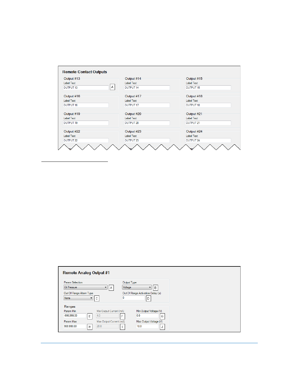
Remote Contact Outputs
To make identifying the contact outputs easier, each of the contact outputs can be given a user-assigned
name
A
.
The remote contact outputs are incorporated into a BESTlogicPlus programmable logic scheme by
selecting them from the I/O group in BESTlogicPlus. For more details, refer to Section 5, BESTlogicPlus
Programmable Logic.
The BESTCOMSPlus Remote Contact Outputs screen is illustrated in Figure 4-43.
Figure 4-43. Remote Contact Outputs
A
Label Text: An alphanumeric character string with a maximum of 16 characters.
Remote Analog Outputs
An optional AEM-2020 (Analog Expansion Module) provides four analog outputs.
Make a parameter selection
A
and select the output type
B
. When enabled, an out of range alarm
C
alerts the
user of an open or damaged analog output wire. An out of range activation delay
D
setting delays alarm
annunciation.
Ranges must be set for the selected output type. Param Min
E
correlates to Min Output Current
F
or Min
Output Voltage
G
and Param Max
H
correlates to Max Output Current
I
or Max Output Voltage
J
.
A remote analog output is disabled when Alarm Configuration is set to “None”. Remote analog output
status is available in BESTlogicPlus Programmable Logic when “Status Only” is selected.
The remote analog outputs are incorporated into a BESTlogicPlus programmable logic scheme by
selecting them from the I/O group in BESTlogicPlus. For more details, refer to Section 5, BESTlogicPlus
Programmable Logic.
The BESTCOMSPlus Remote Analog Output #1 screen is illustrated in Figure 4-44.
Figure 4-44. Remote Analog Output #1
9400200990 Rev X
DGC-2020 BESTCOMSPlus
® Software
4-49