Analog outputs -8, Table 9-3. analog output terminals -8, N figure 9-4 – Basler Electric DGC-2020 User Manual
Page 378: N figure 9-5, Lsm-2020, Analog outputs, 4 – 20 ma current transducer, 0 – 10 vdc voltage transducer
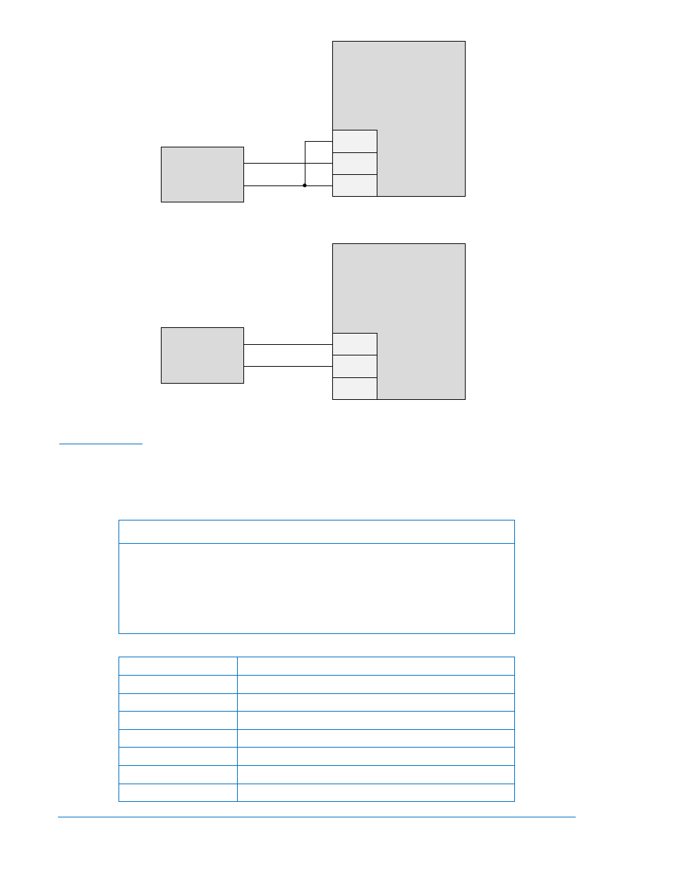
Figure 9-4. Analog Inputs - Current Input Connections
Figure 9-5. Analog Inputs - Voltage Input Connections
Analog Outputs
The LSM-2020 has three sets of analog output contacts: AVR control, GOV control, and Load Share Line.
The AVR control output contacts provide remote control of the generator voltage setpoint. The GOV
control output contacts provide remote control of the generator speed (RPM) setpoint. The generator uses
the measured LS (Load Share Line) output to calculate the per unitized average load level, and uses that
as the set point for its kW controller. Analog input terminals are listed in Table 9-3.
Note
To comply with the requirements of EN 61000-4-6 (RF Conducted Immunity),
wiring connected to LSM-2020 terminals GOV+ and GOV– must be routed
away from the LSM-2020 unit, making no contact with any part of it except the
GOV+ and GOV– terminals. If this is not possible, the wiring must either be
shielded or twisted pair. If shielding is used, it is not required to be grounded. If
the wires are a twisted pair, two turns per inch are required.
Table 9-3. Analog Output Terminals
Terminal
Description
P2-18 (AVR+)
AVR control output positive
P2-17 (AVR–)
AVR control output negative
P2-16 (AVR’)
Provides additional landing point for external resistor
P2-15 (GOV+)
GOV control output positive
P2-14 (GOV–)
GOV control output negative
P2-13 (GOV’)
Provides additional landing point for external resistor
P2-6 (LS+)
Load share line positive
P2-9 (V+)
P2-8 (IN–)
P2-7 (IN+)
LSM-2020
P
0
0
5
9
-8
0
4 – 20 mA
Current
Transducer
P2-9 (V+)
P2-8 (IN–)
P2-7 (IN+)
LSM-2020
P
0
0
5
9
-8
1
0 – 10 Vdc
Voltage
Transducer
9-8
DGC-2020 LSM-2020 (Load Share Module)
9400200990 Rev X