Automatic synchronizer (optional), Automatic synchronizer (optional) -79, Figure 4-64. synchronizer screen -79 – Basler Electric DGC-2020 User Manual
Page 189: Figure 4-65. slip frequency error -79, Frequency correction
Q
Bus Stable Underfrequency Pickup and Dropout: Adjustable from 46 to 64 Hz in 0.05 Hz increments for
50/60 Hz generator frequency (style number x1xxxxxxx).
R
Bus Stable Activation Delay: Adjustable from 0.1 to 600 s in 0.1 s increments.
S
Bus Failed Activation Delay: Adjustable from 0.1 to 600 s in 0.1 s increments.
T
Low Line Scale Factor: Adjustable from 0.001 to 3 in increments of 0.001.
U
Alternate Frequency Scale Factor: 0.001 to 100 in increments of 0.001.
V
Dead Bus Threshold (Per Unit): Range varies based on the values of the native unit setting and the
associated rated data parameter.
Automatic Synchronizer (Optional)
Two methods of generator synchronization are offered: phase lock loop and anticipatory
A
. In both
methods, the DGC-2020 adjusts the frequency and voltage of the generator to match that of the bus
(mains) and then connects the generator to the bus by closing the breaker. Anticipatory mode has the
added capability of compensating for the breaker closing time (the delay between when a breaker close
command is issued and the breaker blades close). The DGC-2020 calculates the advance phase angle
that is required to compensate for the breaker closure time by monitoring the frequency difference
between the generator and the bus.
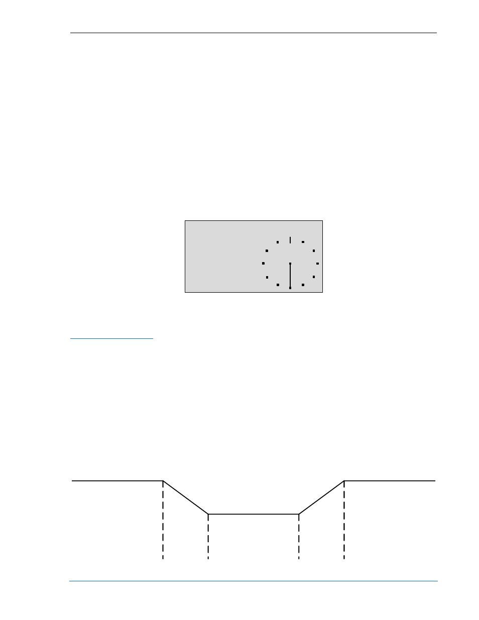
A synchronizer metering screen is available on the front panel HMI under Metering, Generator,
Synchronizer. See Figure 4-64.
Figure 4-64. Synchronizer Screen
The BESTCOMSPlus Synchronizer screen is illustrated in Figure 4-66.
Frequency Correction
Generator frequency correction is defined by the slip frequency setting and further refined by the breaker
closing angle setting. The slip frequency setting
B
establishes the maximum allowable deviation of the
generator speed (frequency) from the bus frequency. The Min Slip Control Limit setting
C
and Max Slip
Control Limit setting
D
are used to calculate the slip frequency error and to provide continuous slip
frequency control while in phase lock synchronization. If the slip frequency magnitude is above the Max
Slip Control Limit, the error is set equal to the Max Error in the opposite polarity. If the slip frequency
magnitude is below the Min Slip Control Limit, the slip frequency error is 0. When it is between the two
limits, the error is calculated internally by the DGC-2020. Slip frequency error is shown in Figure 4-65. To
minimize the impact on the bus during synchronization, the Fgen>Fbus setting
E
can be enabled to force
the generator frequency to exceed the bus frequency at the moment of breaker closure. If this is the case,
the DGC-2020 will drive the generator frequency higher than the bus frequency before closing the
breaker. The breaker closing angle setting
F
defines the maximum allowable phase angle difference
between the generator and the bus. For breaker closure to be considered, the slip angle must remain
below this setting for the duration of the sync activation delay setting
G
.
Figure 4-65. Slip Frequency Error
SYNCHRONIZER
∠°
180 .0
∆Hz 0.00
∆V 0
STATUS OFF
P0057-87
Slip Error
= Max (-)
Slip Error
= Max (+)
Slip Error = 0
P0064-49
9400200990 Rev X
DGC-2020 BESTCOMSPlus
® Software
4-79