Components -17 – Basler Electric DGC-2020 User Manual
Page 245
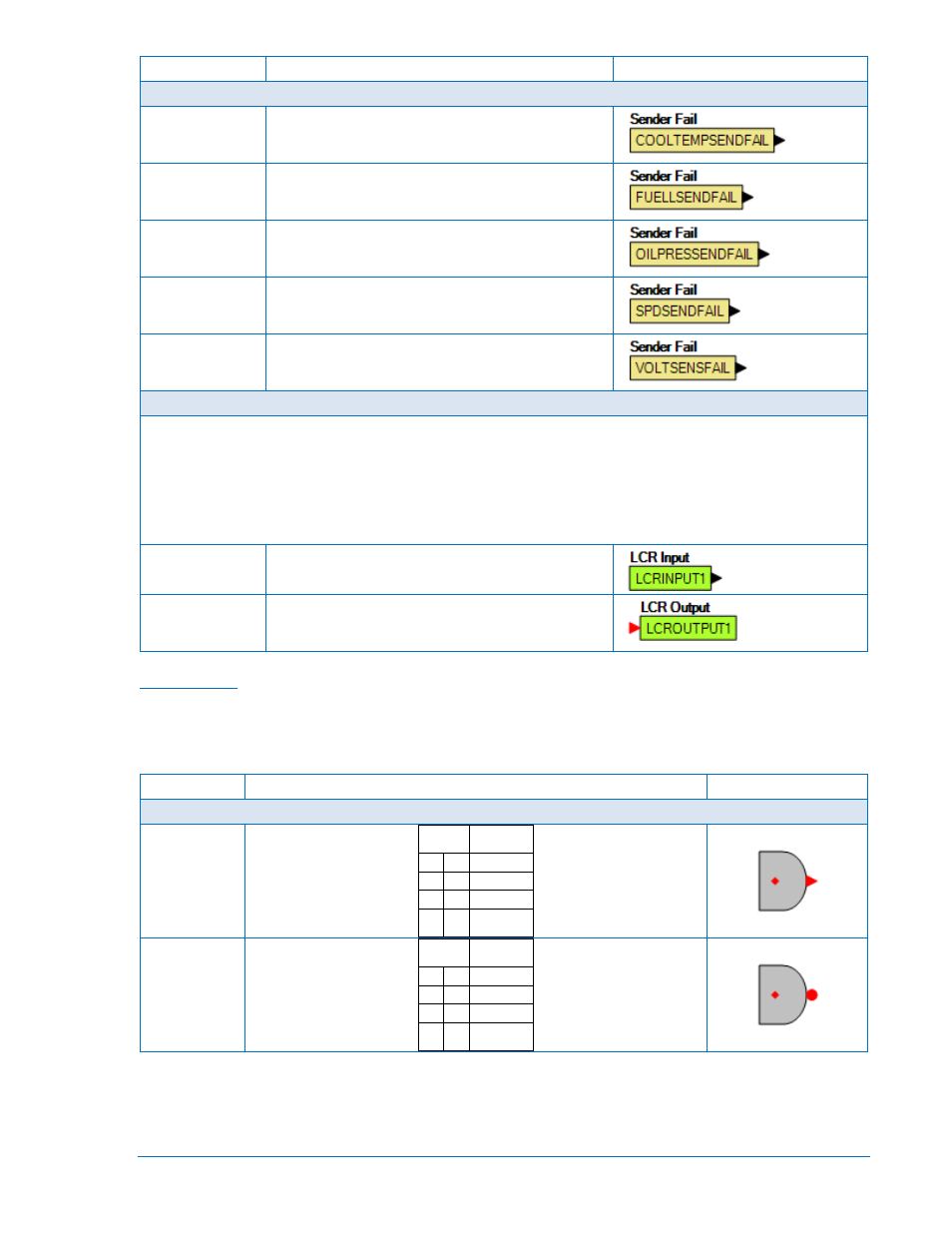
Name
Description
Symbol
Senders
Coolant Temp
Sender Fail
True when the Coolant Temp Sender Fail is
configured as either a pre-alarm or alarm and the
activation delay has expired.
Fuel Level
Sender Fail
True when the Fuel Level Sender Fail is configured
as either a pre-alarm or alarm and the activation
delay has expired.
Oil Pressure
Sender Fail
True when the Oil Pressure Sender Fail is configured
as either a pre-alarm or alarm and the activation
delay has expired.
Speed Sender
Fail
True when the Speed Sender Fail activation delay
has expired.
Voltage Sensing
Fail
True when the Voltage Sensing Fail is configured as
either a pre-alarm or alarm and the activation delay
has expired.
Logic Control Relays
The logic control relays (LCR) consist of LCR outputs and LCR inputs. You can use the output to terminate the
“output” end of a logic network, and then use the corresponding input as an input to logic elsewhere in the logic
scheme. When a given LCR output is true the corresponding LCR input is true. In other words, when LCR Output
N (N being a number from 1 to 16) becomes true, then LCR Input N is true also.
If you get a “too many logic levels” error while building a logic network, LCR outputs and inputs can be used as a
solution to this problem. Place an LCR output on the end of the partial logic network and then use the
corresponding LCR input to build more logic than was previously possible.
Inputs
Input 1-16
See description above.
Outputs
Output 1-16
See description above.
Components
This group contains Logic Gates, Pickup and Dropout Timers, Latches, and Comment Blocks. Table 5-2
lists the names and descriptions of the objects in the Components group.
Table 5-2. Components Group, Names and Descriptions
Name
Description
Symbol
Logic Gates
AND
Input Output
0 0
0
0 1
0
1 0
0
1 1
1
NAND
Input Output
0 0
1
0 1
1
1 0
1
1 1
0
9400200990 Rev X
DGC-2020 BESTlogic
™
Plus Programmable Logic
5-17