Figure 4-67. avr bias control settings -83 – Basler Electric DGC-2020 User Manual
Page 193
Ramp rate
II
is defined as the rate, in percentage of machine capacity, at which the machine will ramp up
its var/PF when loading or coming online. The machine also uses this rate to unload prior to cooling
down. If a machine is the only machine online, ramping will not be in effect.
After ramping a generator's kvar output, to bring it online or offline, overshoot may occur. The likeliness of
kvar overshoot increases as the ramp rate increases. Typically, overshoot is reduced by lowering the
ramp rate to the slowest possible setting. If overshoot is still a problem, the Ramp Overshoot Reduction
JJ
setting can be used. A setting of 0% overshoot reduction results in no change to the amount of overshoot.
A setting of 100% provides maximum overshoot reduction. Ramp Overshoot Reduction must be tuned to
the optimal level. Too little reduction may result in overshoot while too much reduction may result in
undershoot.
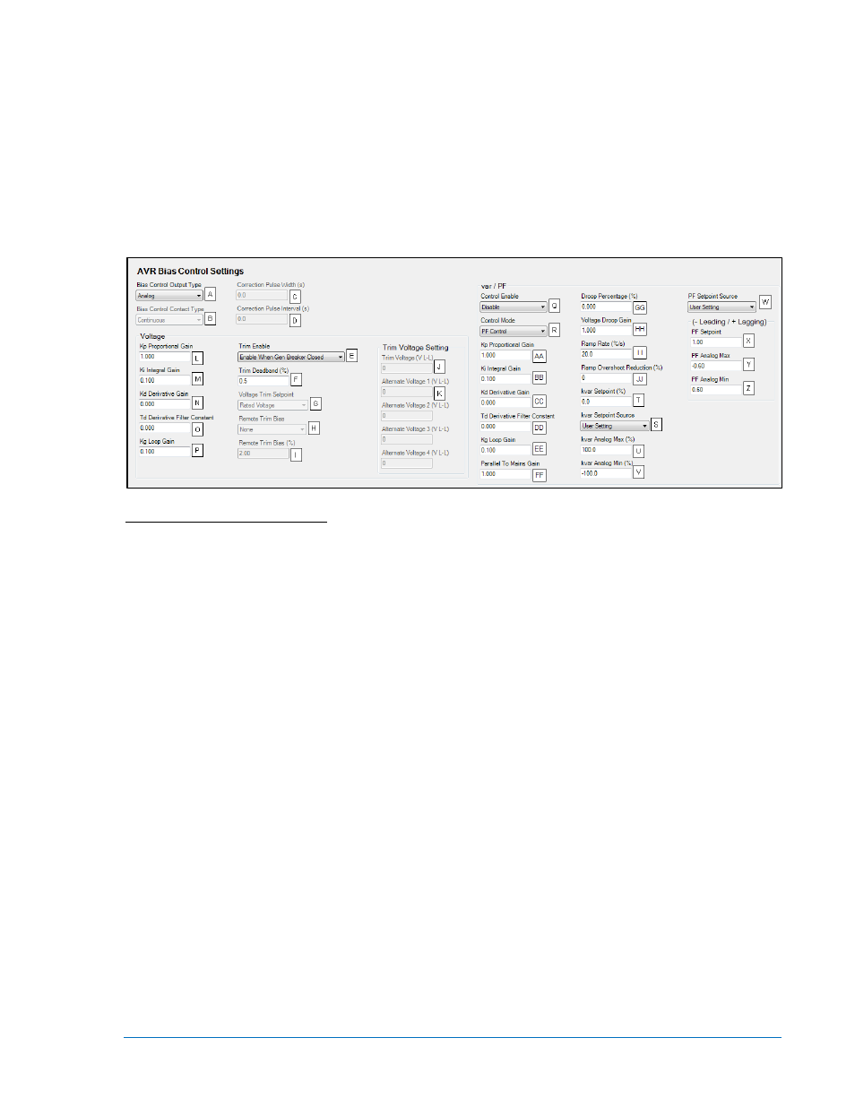
The BESTCOMSPlus AVR Bias Control Settings screen is illustrated in Figure 4-67.
Figure 4-67. AVR Bias Control Settings
A
Bias Control Output Type: Contact or Analog.
B
Bias Control Contact Type: Continuous or Proportional.
C
Correction Pulse Width: Adjustable from 0 to 99.9 s in 0.1 s increments.
D
Correction Pulse Interval: Adjustable from 0 to 99.9 s in 0.1 s increments.
E
Trim Enable: Disable, Enable, or Enable When Gen Breaker Closed (Rev 3 hardware only).
F
Trim Deadband: Adjustable from 0 to 2 percent in increments of 0.1.
G
Voltage Trim Setpoint: Rated Voltage or Trim Voltage Setting.
H
Remote Trim Bias: None, LSM Analog Input 1, or ALG IN 1 through 8.
I
Remote Trim Bias: Adjustable from 0 to 10 percent in increments of 0.01.
J
Trim Voltage: Adjustable from 0 to 99,999 V
L-L
in increments of 1.
K
Alternate Voltage 1-4: Adjustable from 0 to 99,999 V
L-L
in increments of 0.01.
L
Proportional Gain (Kp): Adjustable from 0 to 1,000 in increments of 0.001.
M
Integral Gain (Ki): Adjustable from 0 to 1,000 in increments of 0.001.
N
Derivative Gain (Kd): Adjustable from 0 to 1,000 in increments of 0.001.
O
Derivative Filter Constant (Td): Adjustable from 0 to 1 in increments of 0.001.
P
Loop Gain (Kg): Adjustable from 0 to 1,000 in increments of 0.001.
Q
Control: Disable or Enable.
R
Control Mode: var Control or PF Control.
S
kvar Setpoint Source: User Setting, LSM Analog Input 1, or Analog Inputs 1-8.
T
kvar Setpoint: Adjustable from
–100 to 100 percent in 0.1% increments.
U
kvar Analog Max: Adjustable from 0 to 100 percent in 0.1% increments.
V
kvar Analog Min: Adjustable from 0 to 100 percent in 0.1% increments.
W
PF Setpoint Source: User Setting, LSM Analog Input 1, or Analog Inputs 1-8.
X
PF Setpoint: Adjustable from –0.60 to 0.60 in increments of 0.01.
Y
PF Analog Max: Adjustable from –0.60 to 0.60 in increments of 0.01.
Z
PF Analog Min: Adjustable from –0.60 to 0.60 in increments of 0.01.
AA
Proportional Gain (Kp): Adjustable from 0 to 1,000 in increments of 0.001.
BB
Integral Gain (Ki): Adjustable from 0 to 1,000 in increments of 0.001.
CC
Derivative Gain (Kd): Adjustable from 0 to 1,000 in increments of 0.001.
DD
Derivative Filter Constant (Td): Adjustable from 0 to 1 in increments of 0.0001.
EE
Loop Gain (Kg): Adjustable from 0 to 1,000 in increments of 0.001.
9400200990 Rev X
DGC-2020 BESTCOMSPlus
® Software
4-83