Block diagram, Nxp semiconductors – NXP Semiconductors LPC24XX UM10237 User Manual
Page 747
UM10237_4
© NXP B.V. 2009. All rights reserved.
User manual
Rev. 04 — 26 August 2009
747 of 792
NXP Semiconductors
UM10237
Chapter 34: LPC24XX Embedded Trace Module (ETM)
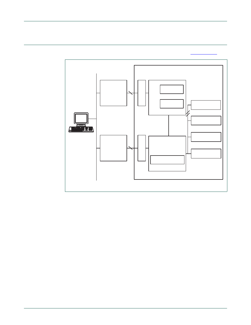
7.
Block diagram
The block diagram of the ETM debug environment is shown below in
Fig 148. ETM debug environment block diagram
PERIPHERAL
TRACE
PORT
ANALYZER
TRACE
10
Host
running
debugger
LAN
JTAG
INTERFACE
UNIT
CONNECTOR
TRIGGER
ETM
PERIPHERAL
RAM
ROM
EMBEDDED ICE
ARM
5
CONNECTOR
APPLICATION PCB