12 i2c state service routines, Section 22–9.12.1, Figure 22–125 – NXP Semiconductors LPC24XX UM10237 User Manual
Page 602: Figure 22–126, Nxp semiconductors, 12 i, C state service routines, 1 initialization
UM10237_4
© NXP B.V. 2009. All rights reserved.
User manual
Rev. 04 — 26 August 2009
602 of 792
NXP Semiconductors
UM10237
Chapter 22: LPC24XX I
2
C interfaces I
2
C0/1/2
9.12 I
2
C State service routines
This section provides examples of operations that must be performed by various I
2
C state
service routines. This includes:
•
Initialization of the I
2
C block after a Reset.
•
I
2
C Interrupt Service.
•
The 26 state service routines providing support for all four I
2
C operating modes.
9.12.1 Initialization
In the initialization example, the I
2
C block is enabled for both master and slave modes.
For each mode, a buffer is used for transmission and reception. The initialization routine
performs the following functions:
•
I2ADR is loaded with the part’s own slave address and the general call bit (GC).
•
The I
2
C interrupt enable and interrupt priority bits are set.
•
The slave mode is enabled by simultaneously setting the I2EN and AA bits in I2CON
and the serial clock frequency (for master modes) is defined by loading CR0 and CR1
in I2CON. The master routines must be started in the main program.
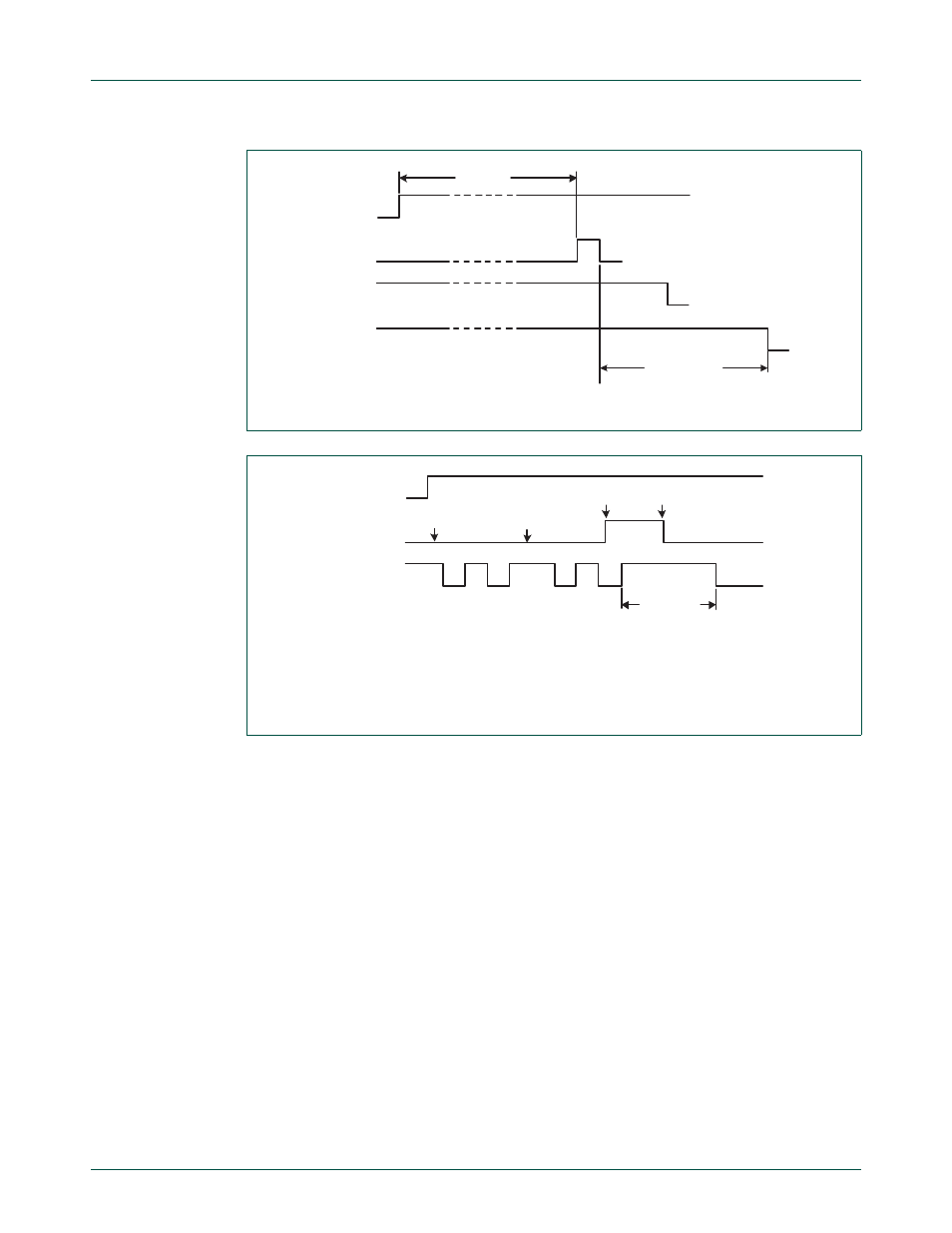
Fig 125. Forced access to a busy I
2
C bus
(1) Unsuccessful attempt to send a start condition.
(2) SDA line is released.
(3) Successful attempt to send a start condition. State 08H is entered.
Fig 126. Recovering from a bus obstruction caused by a low level on SDA
SDA line
SCL line
STA flag
STO flag
time limit
start
condition
SDA line
SCL line
(1)
(2)
(1)
(3)
STA flag
start
condition