2 master receiver mode, Nxp semiconductors – NXP Semiconductors LPC24XX UM10237 User Manual
Page 575
UM10237_4
© NXP B.V. 2009. All rights reserved.
User manual
Rev. 04 — 26 August 2009
575 of 792
NXP Semiconductors
UM10237
Chapter 22: LPC24XX I
2
C interfaces I
2
C0/1/2
6.2 Master Receiver mode
In the master receiver mode, data is received from a slave transmitter. The transfer is
initiated in the same way as in the master transmitter mode. When the START condition
has been transmitted, the interrupt service routine must load the slave address and the
data direction bit to the I
2
C Data Register (I2DAT), and then clear the SI bit. In this case,
the data direction bit (R/W) should be 1 to indicate a read.
When the slave address and data direction bit have been transmitted and an
acknowledge bit has been received, the SI bit is set, and the Status Register will show the
status code. For master mode, the possible status codes are 0x40, 0x48, or 0x38. For
slave mode, the possible status codes are 0x68, 0x78, or 0xB0. For details, refer to
After a repeated START condition, I
2
C may switch to the master transmitter mode.
Fig 112. Format in the Master Transmitter mode
A = Acknowledge (SDA low)
A = Not acknowledge (SDA high)
S = START condition
P = STOP condition
S
SLAVE ADDRESS
RW
A
DATA
A
A/A
P
data transferred
(n Bytes + Acknowledge)
“0” - write
“1” - read
from Master to Slave
from Slave to Master
DATA
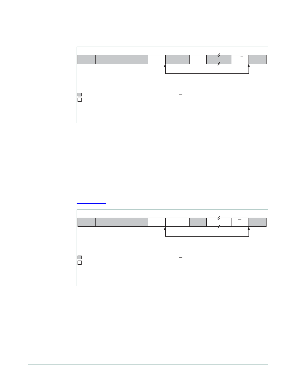
Fig 113. Format of Master Receive mode
DATA
A = Acknowledge (SDA low)
A = Not acknowledge (SDA high)
S = START condition
P = STOP condition
S
SLAVE ADDRESS
R
A
DATA
P
data transferred
(n Bytes + Acknowledge)
“0” - write
“1” - read
from Master to Slave
from Slave to Master
A
A