Figure 15–62, Nxp semiconductors, Chapter 15: lpc24xx usb otg controller – NXP Semiconductors LPC24XX UM10237 User Manual
Page 416
UM10237_4
© NXP B.V. 2009. All rights reserved.
User manual
Rev. 04 — 26 August 2009
416 of 792
NXP Semiconductors
UM10237
Chapter 15: LPC24XX USB OTG controller
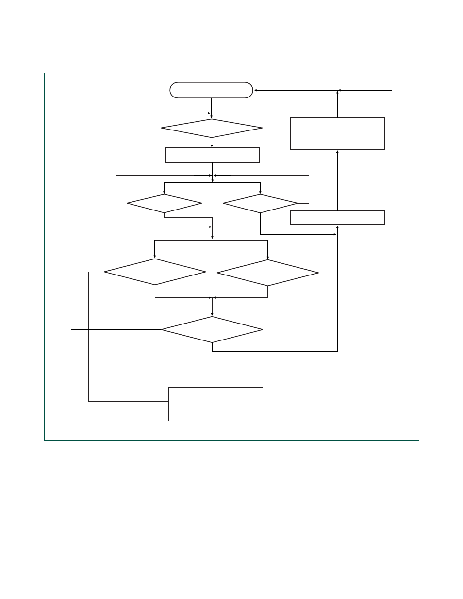
shows the actions that the OTG software stack should take in response to
the hardware actions setting TMR, HNP_SUCCESS, and HNP_FAILURE. The
relationship of the software actions to the Dual-Role A-Device states is also shown.
A-device states are shown in bold font with a circle around them.
Fig 62. Hardware support for A-device switching from host state to peripheral state
disconnect host controller from U1
set HNP_FAILURE,
clear A_HNP_TRACK
clear A_HNP_TRACK
set HNP_SUCCESS
connect device to U1 by clearing
PORT_FUNC[0]
bus reset detected?
OTG timer expired?
(TMR =1 )
resume detected?
connnect host controller back to U1
no
no
no
yes
yes
yes
yes
yes
idle
A_HNP_TRACK = 0
bus suspended ?
resume detected ?
no
no
A_HNP_TRACK = 1 ?
no