Ethernet architecture, Nxp semiconductors – NXP Semiconductors LPC24XX UM10237 User Manual
Page 213
UM10237_4
© NXP B.V. 2009. All rights reserved.
User manual
Rev. 04 — 26 August 2009
213 of 792
NXP Semiconductors
UM10237
Chapter 11: LPC24XX Ethernet
– Memory traffic optimized by buffering and pre-fetching.
•
Enhanced Ethernet features:
– Receive filtering.
– Multicast and broadcast frame support for both transmit and receive.
– Optional automatic FCS insertion (CRC) for transmit.
– Selectable automatic transmit frame padding.
– Over-length frame support for both transmit and receive allows any length frames.
– Promiscuous receive mode.
– Automatic collision backoff and frame retransmission.
– Includes power management by clock switching.
– Wake-on-LAN power management support allows system wake-up: using the
receive filters or a magic frame detection filter.
•
Physical interface:
– Attachment of external PHY chip through standard Media Independent Interface
(MII) or standard Reduced MII (RMII) interface, software selectable.
– PHY register access is available via the Media Independent Interface Management
(MIIM) interface.
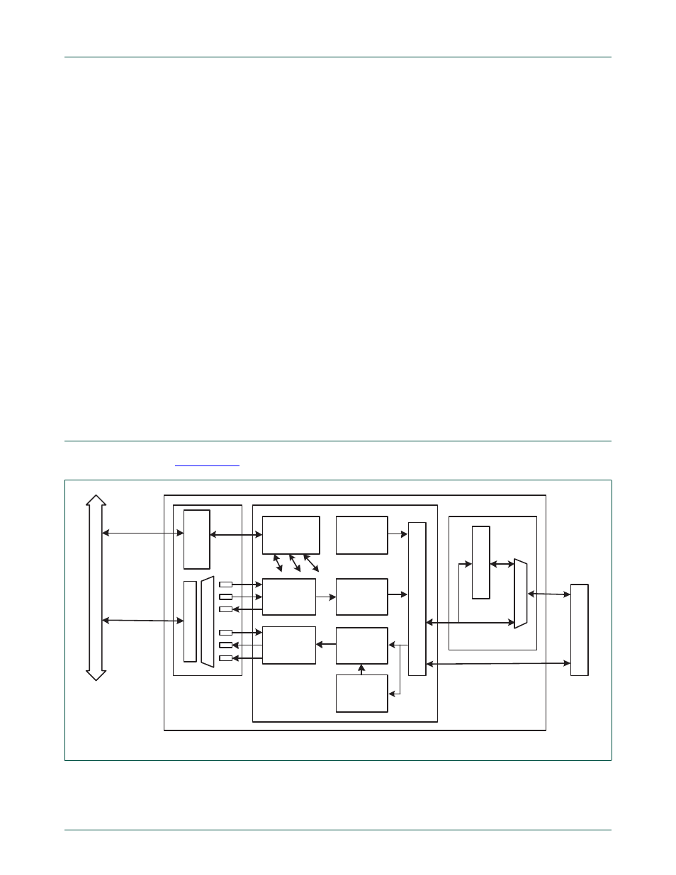
5.
Ethernet architecture
shows the internal architecture of the Ethernet block.
The block diagram for the Ethernet block consists of:
Fig 26. Ethernet block diagram
register
interface (AHB
slave)
DMA interface
(AHB master)
BU
S I
N
T
E
R
F
AC
E
RECEIVE
DMA
TRANSMIT
DMA
RECEIVE
BUFFER
RECEIVE
FILTER
TRANSMIT
RETRY
TRANSMIT
FLOW
CONTROL
E
T
HE
RNE
T
M
A
C
R
M
II A
D
A
P
T
E
R
MII or
RMII
MIIM
HOST
REGISTERS
AH
B BU
S
ETHERNET
BLOCK
MII
RMII
E
T
HE
RN
E
T
P
H
Y
BU
S
IN
T
E
R
F
A
C
E