Figure 3–11, Nxp semiconductors, Chapter 3: lpc24xx system control – NXP Semiconductors LPC24XX UM10237 User Manual
Page 33
UM10237_4
© NXP B.V. 2009. All rights reserved.
User manual
Rev. 04 — 26 August 2009
33 of 792
NXP Semiconductors
UM10237
Chapter 3: LPC24XX System control
The various Resets have some small differences. For example, a Power On Reset causes
the value of certain pins to be latched to configure the part.
For more details on Reset, PLL and startup/boot code interaction see
“PLL and startup/boot code interaction”
.
3.2.1 Reset Source Identification Register (RSIR - 0xE01F C180)
This register contains one bit for each source of Reset. Writing a 1 to any of these bits
clears the corresponding read-side bit to 0. The interactions among the four sources are
described below.
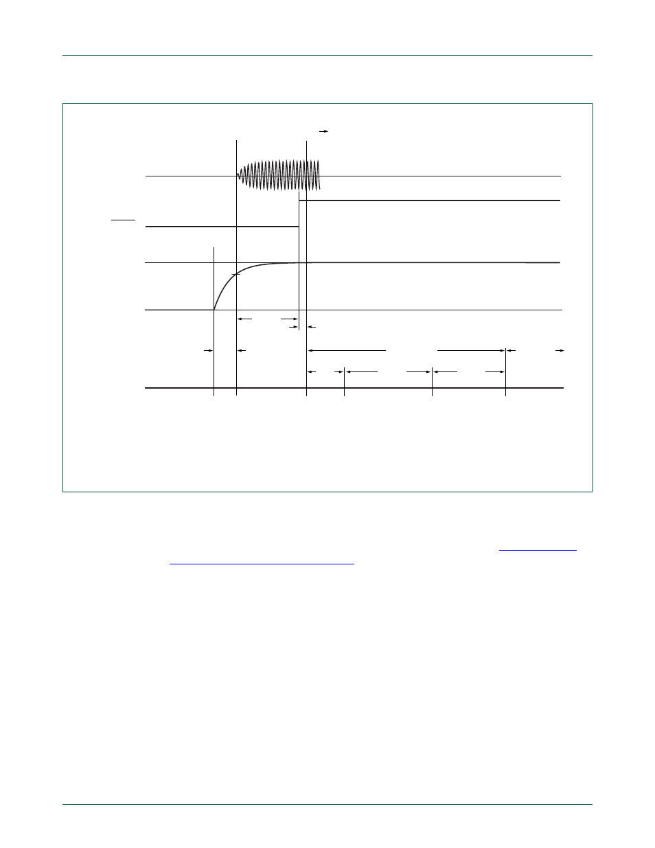
Fig 11. Example of start-up after reset
valid threshold
processor status
V
DD(3V3)
IRC status
RESET
GND
002aad482
30
μs
1
μs; IRC stability count
8
μs
170
μs
160
μs
boot time
user code
boot code
execution
finishes;
user code starts
IRC
starts
IRC
stable
flash read
finishes
flash read
starts
supply ramp-up
time