Nxp semiconductors – NXP Semiconductors LPC24XX UM10237 User Manual
Page 295
UM10237_4
© NXP B.V. 2009. All rights reserved.
User manual
Rev. 04 — 26 August 2009
295 of 792
NXP Semiconductors
UM10237
Chapter 12: LPC24XX LCD controller
When the display point is inside the bounds of the cursor image, the cursor replaces
frame buffer pixels with cursor pixels.
When the last cursor pixel is displayed, an interrupt is generated that software can use as
an indication that it is safe to modify the cursor image. This enables software controlled
animations to be performed without flickering for frame synchronized cursors.
6.5.2 Cursor sizes
Two cursor sizes are supported, as shown in
.
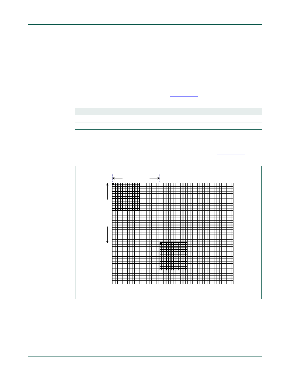
6.5.3 Cursor movement
The following descriptions assume that both the screen and cursor origins are at the top
left of the visible screen (the first visible pixel scanned each frame).
shows
how each pixel coordinate is assumed to be the top left corner of the pixel.
6.5.4 Cursor XY positioning
The CRSR_XY register controls the cursor position on the cursor overlay (see Cursor XY
Position register). This provides separate fields for X and Y ordinates.
The CRSR_CFG register (see Cursor Configuration register) provides a FrameSync bit
controlling the visible behavior of the cursor.
Table 253. Palette data storage for STN monochrome mode.
X Pixels
Y Pixels
Bits per pixel
Words per line
Words in cursor image
32
32
2
2
64
64
64
2
4
256
Fig 37. Cursor movement
CRSR_XY(X)
C
R
SR_
X
Y(Y)
(0,0)