3 transmit buffers (txb), 4 receive buffer (rxb), Nxp semiconductors – NXP Semiconductors LPC24XX UM10237 User Manual
Page 470
UM10237_4
© NXP B.V. 2009. All rights reserved.
User manual
Rev. 04 — 26 August 2009
470 of 792
NXP Semiconductors
UM10237
Chapter 18: LPC24XX CAN controllers CAN1/2
6.3 Transmit Buffers (TXB)
The TXB represents a Triple Transmit Buffer, which is the interface between the Interface
Management Logic (IML) and the Bit Stream Processor (BSP). Each Transmit Buffer is
able to store a complete message which can be transmitted over the CAN network. This
buffer is written by the CPU and read out by the BSP.
6.4 Receive Buffer (RXB)
The Receive Buffer (RXB) represents a CPU accessible Double Receive Buffer. It is
located between the CAN Controller Core Block and APB Interface Block and stores all
received messages from the CAN Bus line. With the help of this Double Receive Buffer
concept the CPU is able to process one message while another message is being
received.
The global layout of the Receive Buffer is very similar to the Transmit Buffer described
earlier. Identifier, Frame Format, Remote Transmission Request bit and Data Length
Code have the same meaning as described for the Transmit Buffer. In addition, the
Receive Buffer includes an ID Index field (see
Section 18–8.9.1 “ID index field”
The received Data Length Code represents the real transmitted Data Length Code, which
may be greater than 8 depending on transmitting CAN node. Nevertheless, the maximum
number of received data bytes is 8. This should be taken into account by reading a
message from the Receive Buffer. If there is not enough space for a new message within
the Receive Buffer, the CAN Controller generates a Data Overrun condition when this
message becomes valid and the acceptance test was positive. A message that is partly
written into the Receive Buffer (when the Data Overrun situation occurs) is deleted. This
situation is signalled to the CPU via the Status Register and the Data Overrun Interrupt, if
enabled.
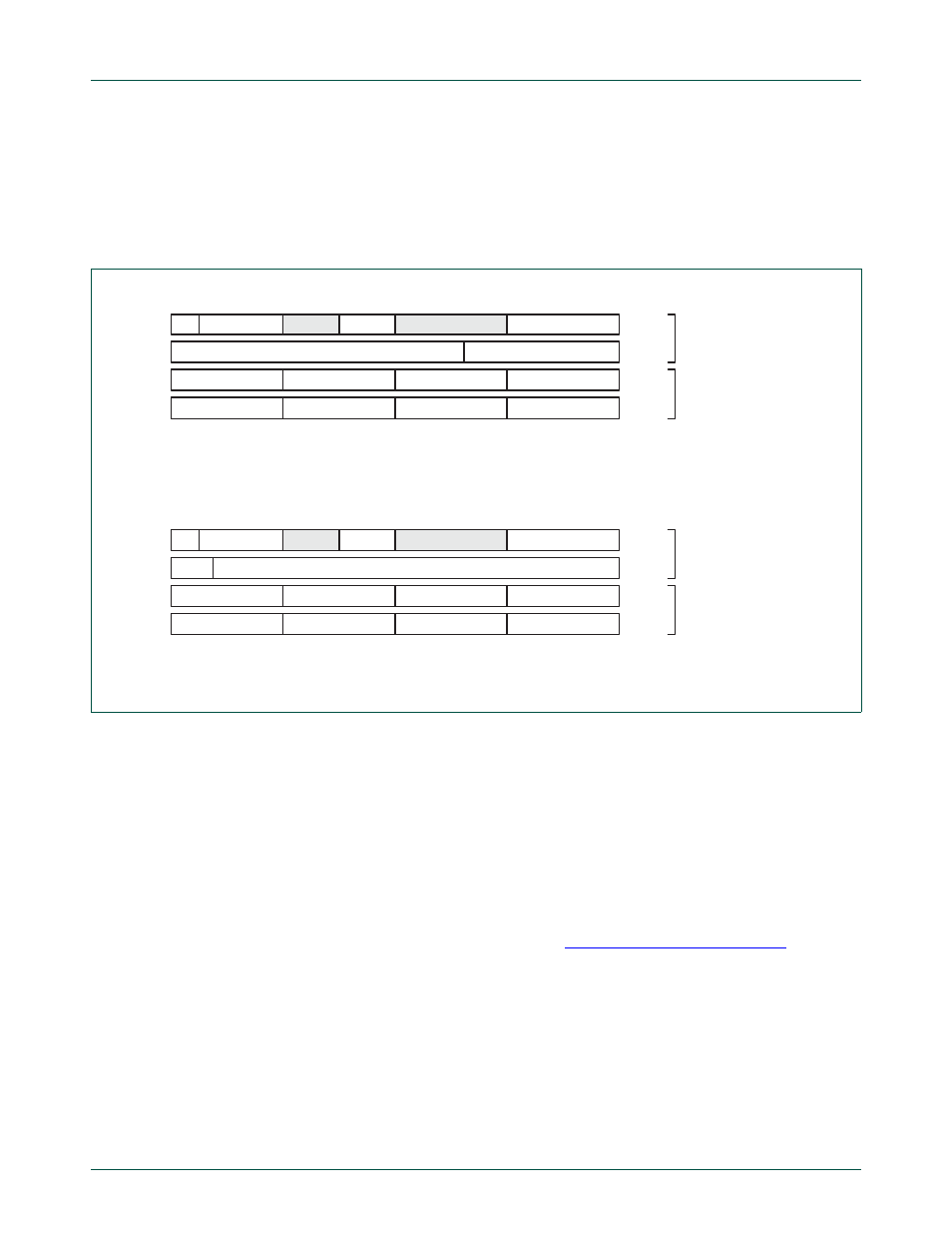
Fig 74. Transmit buffer layout for standard and extended frame format configurations
TX
Frame info
unused
TX Priority
0 . . . 0
ID.28 ... ID.18
TX Data 4
TX Data 3
TX Data 2
TX Data 1
TX Data 8
TX Data 7
TX Data 6
TX Data 5
unused
31
24 23
16 15
8 7
0
TFS
TID
TDA
TDB
Descriptor
Field
Data Field
Standard Frame Format (11-bit Identifier)
Frame info
unused
TX DLC
TX Priority
0 0 0
ID.28 ... ID.00
TX Data 4
TX Data 3
TX Data 2
TX Data 1
TX Data 8
TX Data 7
TX Data 6
TX Data 5
unused
31
24 23
16 15
8 7
0
TFS
TID
TDA
TDB
Descriptor
Field
Data Field
Extended Frame Format (29-bit Identifier)
TX DLC
TX