Functional overview, 1 mutimedia card, 2 secure digital memory card – NXP Semiconductors LPC24XX UM10237 User Manual
Page 552
UM10237_4
© NXP B.V. 2009. All rights reserved.
User manual
Rev. 04 — 26 August 2009
552 of 792
NXP Semiconductors
UM10237
Chapter 21: LPC24XX SD/MMC card interface
There is one additional signal needed in the interface, a power control line MCIPWR, but it
can be sourced from any GPIO signal.
5.
Functional overview
The MCI may be used as a multimedia card bus host (see
) or a secure digital memory card bus host (see
Section 21–5.2 “Secure digital
). Up to 4 multimedia cards (depending on board loading) or a single secure
digital memory card may be connected.
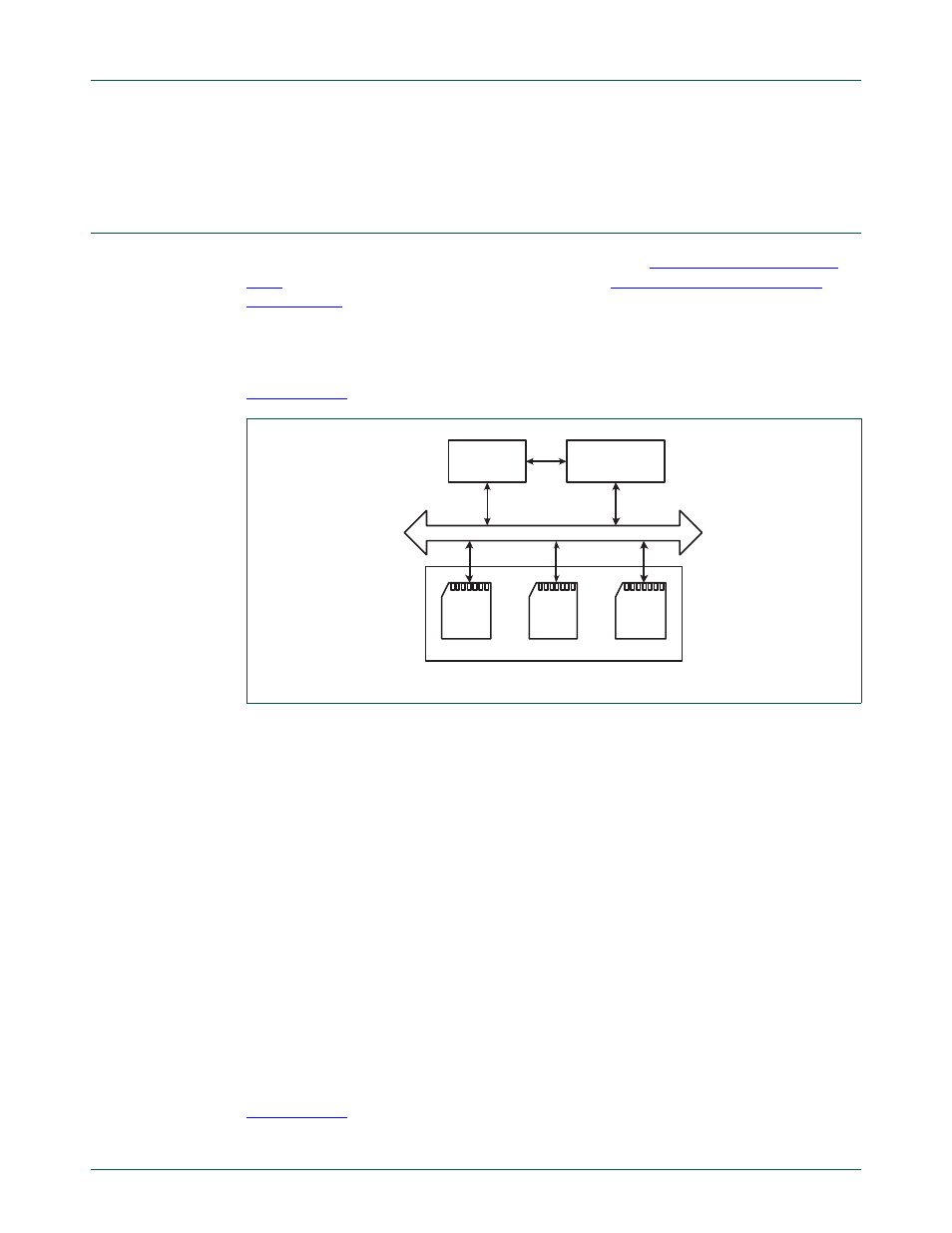
5.1 Mutimedia card
shows the multimedia card system.
Multimedia cards are grouped into three types according to their function:
•
Read Only Memory (ROM) cards, containing pre-programmed data
•
Read/Write (R/W) cards, used for mass storage
•
Input/Output (I/O) cards, used for communication
The multimedia card system transfers commands and data using three signal lines:
•
CLK: One bit is transferred on both command and data lines with each clock cycle.
The clock frequency varies between 0 MHz and 20 MHz (for a multimedia card) or
0 MHz and 25 MHz (for a secure digital memory card).
•
CMD: Bidirectional command channel that initializes a card and transfers commands.
CMD has two operational modes:
– Open-drain for initialization
– Push-pull for command transfer
•
DAT: Bidirectional data channel, operating in push-pull mode
5.2 Secure digital memory card
shows the secure digital memory card connection.
Fig 104. Multimedia card system
MULTIMEDIA CARD BUS
POWER
SUPPLY
MULTIMEDIA
CARD
INTERFACE
MULTIMEDIA CARD STACK
CARD
CARD
CARD