Chapter 9: lpc24xx pin connect, How to read this chapter, Description – NXP Semiconductors LPC24XX UM10237 User Manual
Page 177
UM10237_4
© NXP B.V. 2009. All rights reserved.
User manual
Rev. 04 — 26 August 2009
177 of 792
1.
How to read this chapter
The LPC2400 parts have different pin configurations depending on the number of pins.
See
for the PINSEL registers needed to configure the different LPC2400
parts:
•
Only LPC2470 and LPC2478 have an LCD controller.
•
LPC2420/60 and LPC2470 are flashless and requite boot pins (see
•
LPC2458 has an 16-bit external memory controller, LPC2460/68/70/78 have 32-bit
external memory controller.
•
All parts can have ETM functions enabled or disabled.
•
Ethernet and CAN interface are not available on LPC2420.
2.
Description
The pin connect block allows selected pins of the microcontroller to have more than one
function. Configuration registers control the multiplexers to allow connection between the
pin and the on chip peripherals.
Peripherals should be connected to the appropriate pins prior to being activated, and prior
to any related interrupt(s) being enabled. Activity of any enabled peripheral function that is
not mapped to a related pin should be considered undefined.
Selecting a single function on a port pin completely excludes all other functions otherwise
available on the same pin.
UM10237
Chapter 9: LPC24XX Pin connect
Rev. 04 — 26 August 2009
User manual
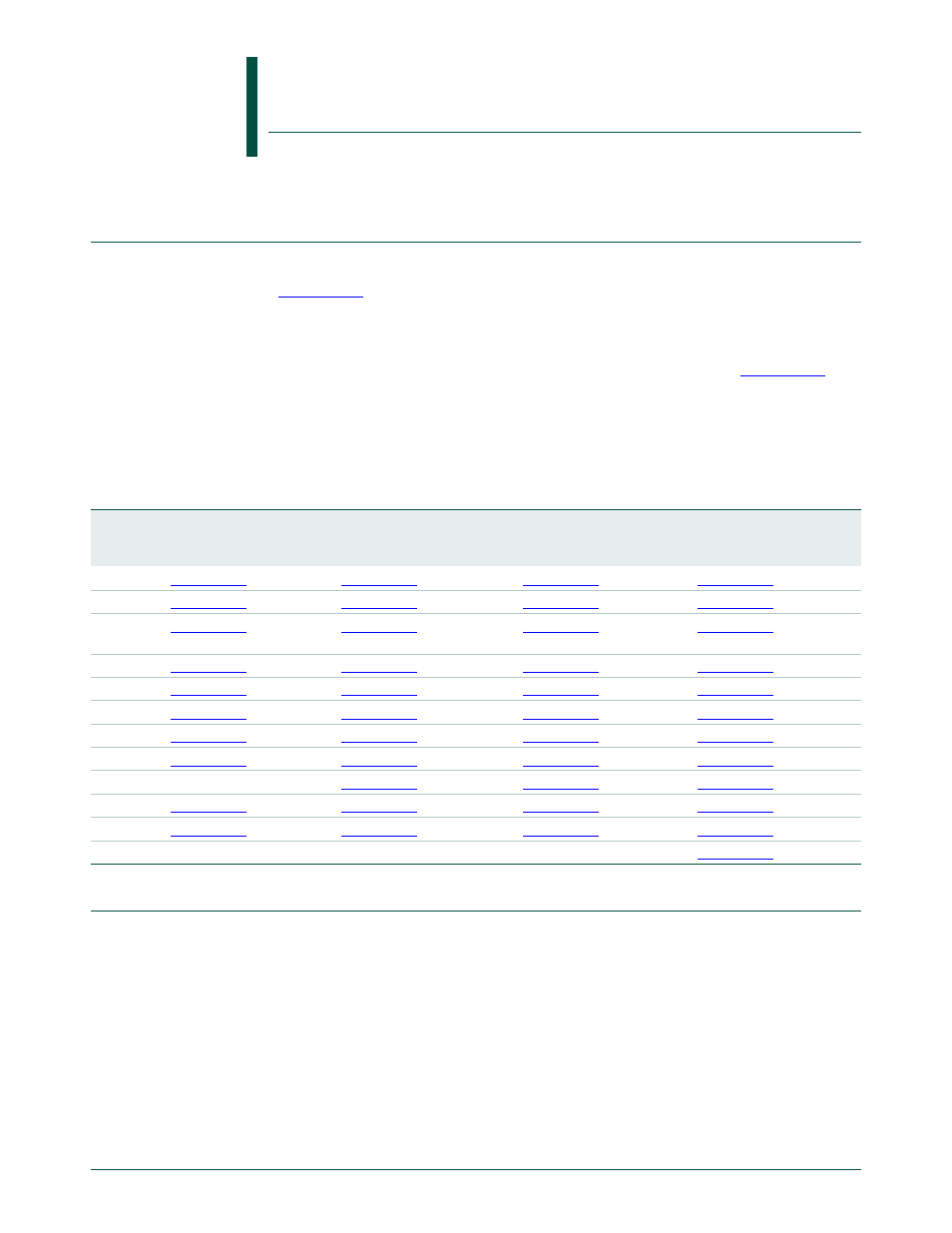
Table 126. LPC2400 PINSEL register use
PINSEL
register
LPC2458
Functions
not
available
LPC2420
Functions
not
available
LPC2460/68 Functions
not
available
LPC2470/78 Functions
not
available
PINSEL0
-
CAN
-
-
PINSEL1
-
-
-
PINSEL2
LCD
Ethernet,
LCD
LCD
-
PINSEL3
LCD
LCD
LCD
-
PINSEL4
LCD
CAN, LCD
LCD
-
PINSEL5
-
-
-
-
PINSEL6
-
-
-
-
PINSEL7
-
-
-
-
PINSEL8
-
-
-
-
-
PINSEL9
LCD
LCD
LCD
-
PINSEL10
-
-
-
-
PINSEL11 -
-
-
-
-
-
-