Nxp semiconductors – NXP Semiconductors LPC24XX UM10237 User Manual
Page 341
UM10237_4
© NXP B.V. 2009. All rights reserved.
User manual
Rev. 04 — 26 August 2009
341 of 792
NXP Semiconductors
UM10237
Chapter 13: LPC24XX USB device controller
9.3.3 USB Device Interrupt Enable register (USBDevIntEn - 0xFFE0 C204)
Writing a one to a bit in this register enables the corresponding bit in USBDevIntSt to
generate an interrupt on one of the interrupt lines when set. By default, the interrupt is
routed to the USB_INT_REQ_LP interrupt line. Optionally, either the EP_FAST or FRAME
interrupt may be routed to the USB_INT_REQ_HP interrupt line by changing the value of
USBDevIntPri. USBDevIntEn is a read/write register.
9.3.4 USB Device Interrupt Clear register (USBDevIntClr - 0xFFE0 C208)
Writing one to a bit in this register clears the corresponding bit in USBDevIntSt. Writing a
zero has no effect.
Remark: Before clearing the EP_SLOW or EP_FAST interrupt bits, the corresponding
endpoint interrupts in USBEpIntSt should be cleared.
USBDevIntClr is a write only register.
6
RxENDPKT
The current packet in the endpoint buffer is transferred to the CPU.
0
7
TxENDPKT
The number of data bytes transferred to the endpoint buffer equals the number of
bytes programmed in the TxPacket length register (USBTxPLen).
0
8
EP_RLZED
Endpoints realized. Set when Realize Endpoint register (USBReEp) or MaxPacketSize
register (USBMaxPSize) is updated and the corresponding operation is completed.
0
9
ERR_INT
Error Interrupt. Any bus error interrupt from the USB device. Refer to
“Read Error Status (Command: 0xFB, Data: read 1 byte)” on page 368
0
31:10 -
Reserved, user software should not write ones to reserved bits. The value read from a
reserved bit is not defined.
NA
Table 299. USB Device Interrupt Status register (USBDevIntSt - address 0xFFE0 C200) bit description
Bit
Symbol
Description
Reset value
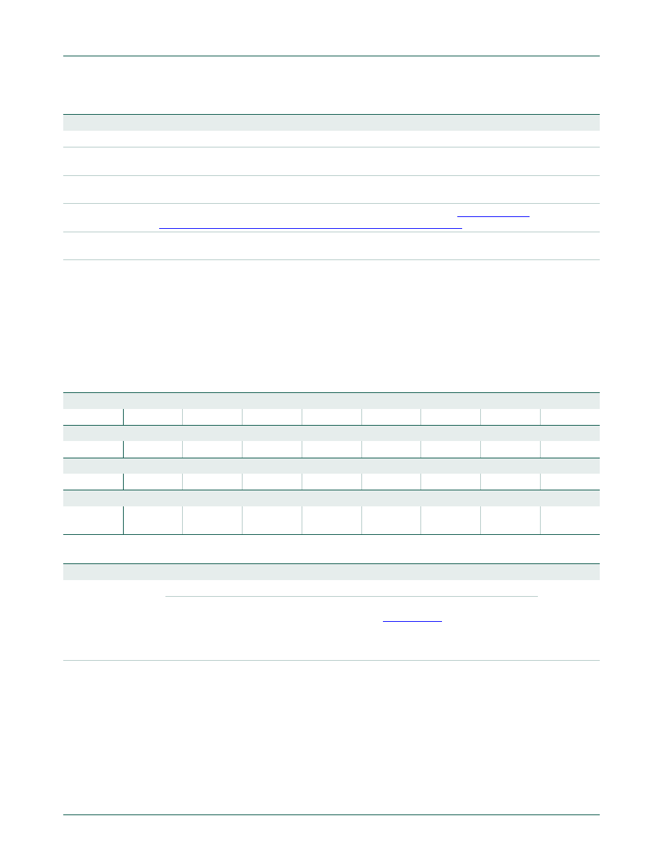
Table 300. USB Device Interrupt Enable register (USBDevIntEn - address 0xFFE0 C204) bit allocation
Reset value: 0x0000 0000
Bit
31
30
29
28
27
26
25
24
Symbol
-
-
-
-
-
-
-
-
Bit
23
22
21
20
19
18
17
16
Symbol
-
-
-
-
-
-
-
-
Bit
15
14
13
12
11
10
9
8
Symbol
-
-
-
-
-
-
ERR_INT
EP_RLZED
Bit
7
6
5
4
3
2
1
0
Symbol
TxENDPKT
Rx
ENDPKT
CDFULL
CCEMPTY
DEV_STAT
EP_SLOW
EP_FAST
FRAME
Table 301. USB Device Interrupt Enable register (USBDevIntEn - address 0xFFE0 C204) bit description
Bit
Symbol
Value
Description
Reset value
31:0
See
USBDevIntEn
bit allocation
table above
0
No interrupt is generated.
0
1
An interrupt will be generated when the corresponding bit in the Device
Interrupt Status (USBDevIntSt) register (
) is set. By default,
the interrupt is routed to the USB_INT_REQ_LP interrupt line. Optionally,
either the EP_FAST or FRAME interrupt may be routed to the
USB_INT_REQ_HP interrupt line by changing the value of USBDevIntPri.