Battery ram, Rtc external 32 khz oscillator component selection, Section 26–9 “rtc external 32 khz – NXP Semiconductors LPC24XX UM10237 User Manual
Page 660: Oscillator component selection, Nxp semiconductors
UM10237_4
© NXP B.V. 2009. All rights reserved.
User manual
Rev. 04 — 26 August 2009
660 of 792
NXP Semiconductors
UM10237
Chapter 26: LPC24XX Real-Time Clock (RTC) and battery RAM
power consumption by using the signal from RTCX1-2 pins, and writing a 0 into the
PCRTC bit in the PCONP power control register (see
Section 4–3.4 “Power control” on
).
Remark: Note that if the RTC is running from the 32 kHz signal and powered by VBAT, the
internal registers can be read. However, they cannot be written to unless the PCRTC bit in
the PCONP register is set to 1, see
.
8.
Battery RAM
The Battery RAM is a 2 kbyte static RAM residing on the APB bus. The address range is
0xE008 4000 to 0xE008 47FF.The SRAM can be accessed word-wise (32-bit) only.
The Battery RAM is powered from the VBAT pin along with the RTC, both of which exist in
a power domain that is isolated from the rest of the chip. This allows them to operate while
the main chip power has been removed.
9.
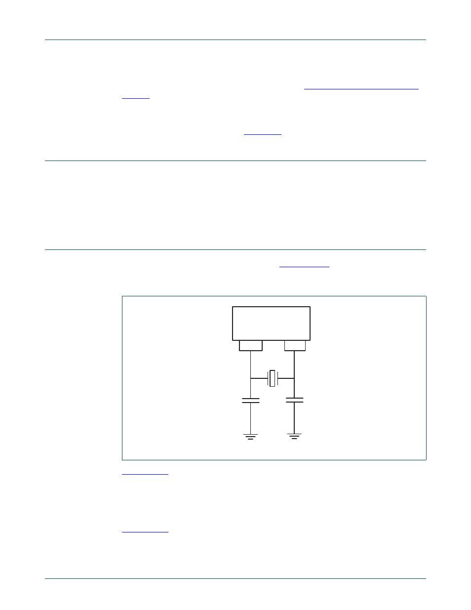
RTC external 32 kHz oscillator component selection
The RTC external oscillator circuit is shown in
. Since the feedback
resistance is integrated on chip, only a crystal, the capacitances C
X1
and C
X2
need to be
connected externally to the microcontroller.
gives the crystal parameters that should be used. C
L
is the typical load
capacitance of the crystal and is usually specified by the crystal manufacturer. The actual
C
L
influences oscillation frequency. When using a crystal that is manufactured for a
different load capacitance, the circuit will oscillate at a slightly different frequency
(depending on the quality of the crystal) compared to the specified one. Therefore for an
accurate time reference it is advised to use the load capacitors as specified in
that belong to a specific C
L
. The value of external capacitances C
X1
and
C
X2
specified in this table are calculated from the internal parasitic capacitances and the
C
L
. Parasitics from PCB and package are not taken into account.
Fig 136. RTC 32 kHz crystal oscillator circuit
RTCX1
RTCX2
LPC24xx
C
X1
C
X2
32 kHz
Xtal