Can controller architecture, 1 apb interface block (aib), 2 interface management logic (iml) – NXP Semiconductors LPC24XX UM10237 User Manual
Page 469: Nxp semiconductors
UM10237_4
© NXP B.V. 2009. All rights reserved.
User manual
Rev. 04 — 26 August 2009
469 of 792
NXP Semiconductors
UM10237
Chapter 18: LPC24XX CAN controllers CAN1/2
6.
CAN controller architecture
The CAN Controller is a complete serial interface with both Transmit and Receive Buffers
but without Acceptance Filter. CAN Identifier filtering is done for all CAN channels in a
separate block (Acceptance Filter). Except for message buffering and acceptance filtering
the functionality is similar to the PeliCAN concept.
The CAN Controller Block includes interfaces to the following blocks:
•
APB Interface
•
Acceptance Filter
•
Vectored Interrupt Controller (VIC)
•
CAN Transceiver
•
Common Status Registers
6.1 APB Interface Block (AIB)
The APB Interface Block provides access to all CAN Controller registers.
6.2 Interface Management Logic (IML)
The Interface Management Logic interprets commands from the CPU, controls internal
addressing of the CAN Registers and provides interrupts and status information to the
CPU.
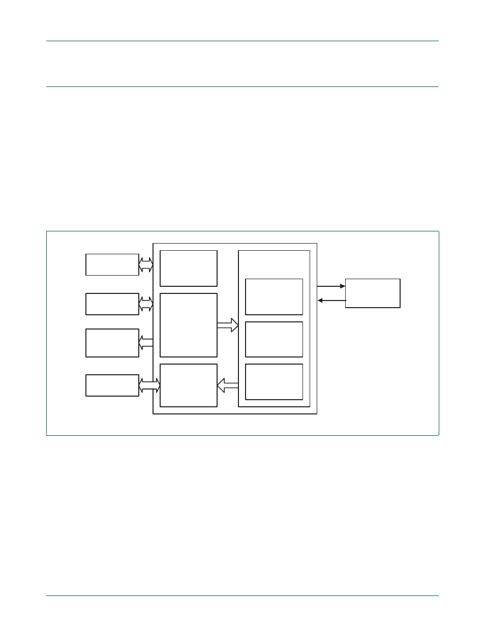
Fig 73. CAN controller block diagram
INTERFACE
MANAGEMENT
LOGIC
TRANSMIT
BUFFERS 1,2
AND 3
RECEIVE
BUFFERS 1
AND 2
BIT
TIMING
LOGIC
BIT
STREAM
PROCESSOR
ERROR
MANAGEMENT
LOGIC
CAN CORE
BLOCK
VIC
APB BUS
ACCEPTANCE
FILTER
COMMON
STATUS
REGISTER
CAN
TRANSCEIVER
TX
RX