6 configuration example 6, Nxp semiconductors – NXP Semiconductors LPC24XX UM10237 User Manual
Page 520
UM10237_4
© NXP B.V. 2009. All rights reserved.
User manual
Rev. 04 — 26 August 2009
520 of 792
NXP Semiconductors
UM10237
Chapter 18: LPC24XX CAN controllers CAN1/2
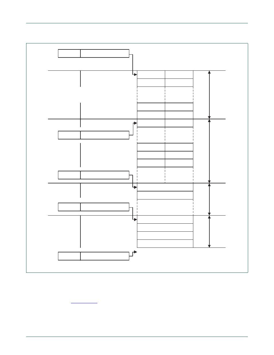
18.6 Configuration example 6
The Table below shows which sections and therefore which types of CAN identifiers are
used and activated. The ID-Look-up Table configuration of this example is shown in
Fig 91. Detailed example of acceptance filter tables and ID index values
SFF_sa
000 d := 000 h := 0 0000 0000 b
ex
pl
ic
it
S
F
F
t
abl
e
lower_boundary 3 4 upper_boundary
lower_boundary 3
lower_boundary 3
5 upper_boundary
6 upper_boundary
0
1
3
2
0
1
2
3
22
23
24
25
26 d
22
23
25
24
2 6
34 d
35 d
36 d
38 d
39 d
38
39
lower_boundary 41
upper_boundary
lower_boundary 42
upper_boundary
41 d
42 d
gr
oup S
F
F
t
a
b
le
ex
pl
ic
it E
F
F
t
abl
e
g
roup E
F
F
t
abl
e
SFF_GRP_sa 52 d := 034 h := 0 0011 0100 b
EFF_sa
100 d := 064 h := 0 0110 0100 b
EFF_GRP_sa 112 d := 070 h := 0 0111 0000 b
ENDofTable
128 d := 080 h := 0 1000 0000 b
APB base +
address
00d = 00h
04d = 04h
44d = 2Ch
48d = 30h
52d = 34h
84d = 54h
88d = 58h
92d = 5Ch
100d = 64h
104d = 68h
112d = 70h
116d = 74h
120d = 78h
124d = 7Ch
column_lower
column_upper
look-up table RAM
ID index #