Nxp semiconductors – NXP Semiconductors LPC24XX UM10237 User Manual
Page 436
UM10237_4
© NXP B.V. 2009. All rights reserved.
User manual
Rev. 04 — 26 August 2009
436 of 792
NXP Semiconductors
UM10237
Chapter 16: LPC24XX UART0/2/3
2. A falling edge on UARTn Rx pin triggers the beginning of the start bit. The rate
measuring counter will start counting pclk cycles.
3. During the receipt of the start bit, 16 pulses are generated on the RSR baud input with
the frequency of the UARTn input clock, guaranteeing the start bit is stored in the
UnRSR.
4. During the receipt of the start bit (and the character LSB for mode = 0) the rate
counter will continue incrementing with the pre-scaled UARTn input clock (pclk).
5. If Mode = 0 then the rate counter will stop on next falling edge of the UARTn Rx pin. If
Mode = 1 then the rate counter will stop on the next rising edge of the UARTn Rx pin.
6. The rate counter is loaded into UnDLM/UnDLL and the baud-rate will be switched to
normal operation. After setting the UnDLM/UnDLL the end of auto-baud interrupt
UnIIR ABEOInt will be set, if enabled. The UnRSR will now continue receiving the
remaining bits of the ”A/a" character.
a. Mode 0 (start bit and LSB are used for auto-baud)
b. Mode 1 (only start bit is used for auto-baud)
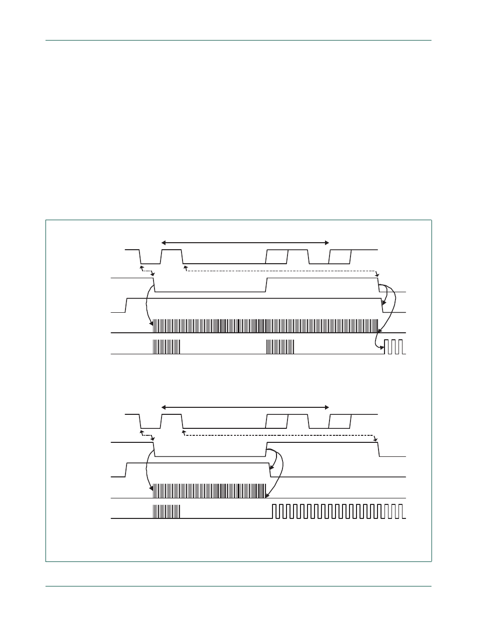
Fig 65. Autobaud a) mode 0 and b) mode 1 waveform
UARTn RX
start bit
LSB of 'A' or 'a'
U0ACR start
rate counter
start
bit0
bit1
bit2
bit3
bit4
bit5
bit6
bit7
parity stop
'A' (0x41) or 'a' (0x61)
16 cycles
16 cycles
16xbaud_rate
UARTn RX
start bit
LSB of 'A' or 'a'
rate counter
'A' (0x41) or 'a' (0x61)
start
bit0
bit1
bit2
bit3
bit4
bit5
bit6
bit7
parity stop
U1ACR start
16 cycles
16xbaud_rate