9 auto-flow control, Nxp semiconductors, 1 auto-rts – NXP Semiconductors LPC24XX UM10237 User Manual
Page 454
UM10237_4
© NXP B.V. 2009. All rights reserved.
User manual
Rev. 04 — 26 August 2009
454 of 792
NXP Semiconductors
UM10237
Chapter 17: LPC24XX UART1
4.9 Auto-flow control
If auto-RTS mode is enabled the UART1‘s receiver FIFO hardware controls the RTS1
output of the UART1. If the auto-CTS mode is enabled the UART1‘s U1TSR hardware will
only start transmitting if the CTS1 input signal is asserted.
4.9.1 Auto-RTS
The auto-RTS function is enabled by setting the RTSen bit. Auto-RTS data flow control
originates in the U1RBR module and is linked to the programmed receiver FIFO trigger
level. If auto-RTS is enabled, the data-flow is controlled as follows:
When the receiver FIFO level reaches the programmed trigger level, RTS1 is deasserted
(to a high value). It is possible that the sending UART sends an additional byte after the
trigger level is reached (assuming the sending UART has another byte to send) because it
might not recognize the deassertion of RTS1 until after it has begun sending the additional
byte. RTS1 is automatically reasserted (to a low value) once the receiver FIFO has
reached the previous trigger level. The reassertion of RTS1 signals to the sending UART
to continue transmitting data.
If Auto-RTS mode is disabled, the RTSen bit controls the RTS1 output of the UART1. If
Auto-RTS mode is enabled, hardware controls the RTS1 output, and the actual value of
RTS1 will be copied in the RTS Control bit of the UART1. As long as Auto-RTS is enabled,
the value of the RTS Control bit is read-only for software.
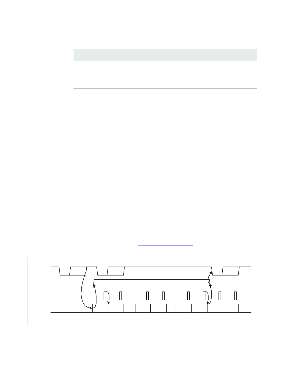
Example: Suppose the UART1 operating in type 550 has trigger level in U1FCR set to 0x2
then if Auto-RTS is enabled the UART1 will deassert the RTS1 output as soon as the
receive FIFO contains 8 bytes (
). The RTS1 output will be
reasserted as soon as the receive FIFO hits the previous trigger level: 4 bytes.
6
RTSen
0
Disable auto-rts flow control.
0
1
Enable auto-rts flow control.
7
CTSen
0
Disable auto-cts flow control.
0
1
Enable auto-cts flow control.
Table 406. UART1 Modem Control Register (U1MCR - address 0xE001 0010) bit description
Bit
Symbol
Value Description
Reset
value
Fig 68. Auto-RTS Functional Timing
start
byte N
stop
start
bits0..7
stop
start
bits0..7
stop
N-1
N
N-1
N-1
N-2
N-2
M+2
M+1
M
M-1
UART1 Rx
RTS1 pin
UART1 Rx
FIFO level
UART1 Rx
FIFO read
~ ~
~ ~
~ ~
~ ~
~ ~