Figure 15–53, Nxp semiconductors – NXP Semiconductors LPC24XX UM10237 User Manual
Page 397
UM10237_4
© NXP B.V. 2009. All rights reserved.
User manual
Rev. 04 — 26 August 2009
397 of 792
NXP Semiconductors
UM10237
Chapter 15: LPC24XX USB OTG controller
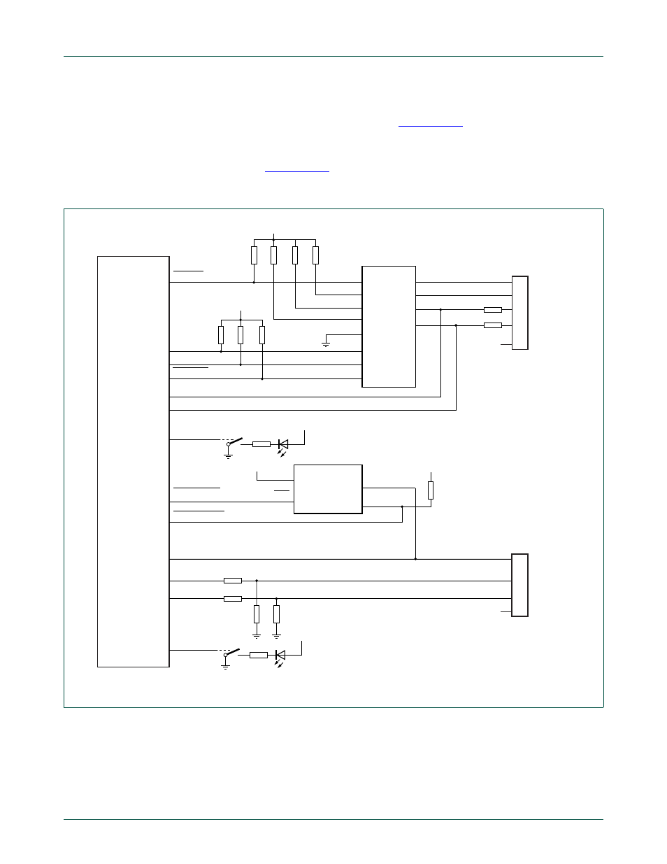
1. Use the internal USB transceiver for USB signalling and use the external OTG
transceiver for OTG functionality only (see
). This option uses the
internal transceiver in VP/VM mode.
2. Use the external OTG transceiver in VP/VM mode for OTG functionality and USB
signalling (see
In both cases port U2 is connected as a host. Solution one uses fewer pins.
Fig 53. USB OTG port configuration: port U1 OTG Dual-Role device, port U2 host
USB_UP_LED1
USB_D+1
USB_D
−1
USB_PWRD2
USB_SDA1
USB_SCL1
RSTOUT
15
k
Ω
15
k
Ω
LPC24XX
USB-A
connector
Mini-AB
connector
33
Ω
33
Ω
33
Ω
33
Ω
V
DD
V
DD
V
DD
USB_UP_LED2
V
DD
USB_OVRCR2
LM3526-L
ENA
IN
5 V
OUTA
FLAGA
V
DD
D+
D
−
V
BUS
USB_PPWR2
USB_D+2
USB_D
−2
002aac708
R7
R4
R5
R6
R1
R2
R3
R4
R8
USB_INT1
RESET_N
ADR/PSW
SPEED
SUSPEND
OE_N/INT_N
SCL
SDA
INT_N
VBUS
ID
DP
DM
ISP1302
V
SS
V
SS