Figure 21–107, When, Nxp semiconductors – NXP Semiconductors LPC24XX UM10237 User Manual
Page 555
UM10237_4
© NXP B.V. 2009. All rights reserved.
User manual
Rev. 04 — 26 August 2009
555 of 792
NXP Semiconductors
UM10237
Chapter 21: LPC24XX SD/MMC card interface
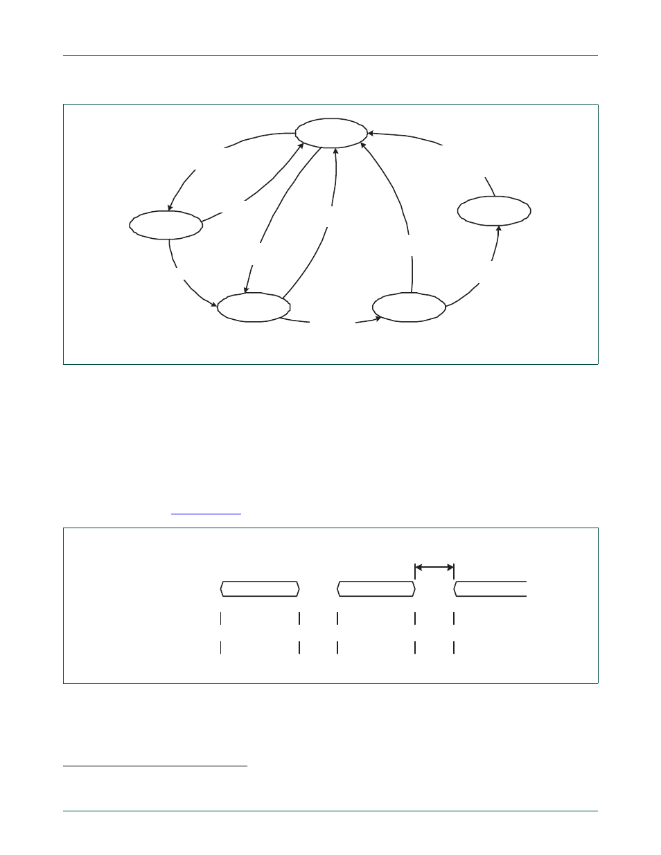
When the WAIT state is entered, the command timer starts running. If the timeout
1
is
reached before the CPSM moves to the RECEIVE state, the timeout flag is set and the
IDLE
2
state is entered.
If the interrupt bit is set in the command register, the timer is disabled and the CPSM waits
for an interrupt request from one of the cards. If a pending bit is set in the command
register, the CPSM enters the PEND state, and waits for a CmdPend signal from the data
path subunit. When CmdPend is detected, the CPSM moves to the SEND state. This
enables the data counter to trigger the stop command transmission.
shows the MCI command transfer.
Fig 107. Command path state machine
IDLE
PEND
SEND
WAIT
RECEIVE
Enabled and
Pending command
Disabled
Enabled and
command start
LastData
Wait for
response
Disabled or
no response
Disabled
or timeout
Response
started
Response received
or disabled or
command CRC failed
1.
The timeout period has a fixed value of 64 MCICLK clocks period.
2.
The CPSM remains in the IDLE state for at least eight MCICLK periods to meet Ncc and Nrc timing constraints.
Fig 108. MCI command transfer
MCICLK
State
MCICMD
COMMAND
RESPONSE
COMMAND
IDLE
SEND
WAIT
RECEIVE
IDLE
SEND
HI-Z
controller drives
HI-Z
card drives
HI-Z
controller drives
min 8
MCICLK