1 motion fixed parameter details, 1 ) run mode – Yaskawa MP2000 Series: Built-in SVB or SVB-01 Motion Module User Manual
Page 94
4.4 MP2000 Series Machine Controller Parameter Details
4.4.1 Motion Fixed Parameter Details
4-18
4.4 MP2000 Series Machine Controller Parameter Details
This section provides details for each motion parameter (fixed parameters, setting parameters, and monitoring parame-
ters).
4.4.1 Motion Fixed Parameter Details
The following tables provide details of motion fixed parameters.
Refer to 4.3.1 Fixed Parameter List for a list of motion fixed parameters.
in the following tables indicates that the item is also compatible with SVR.
The software versions with which the parameters for linear type can be set for SVR are limited to:
• MP2000 series Machine Controller software version 2.50 or later
• MPE720 version 5.37 or later
( 1 ) Run Mode
Terminology: Store
The use of “store” here refers to information that is automatically transferred by the CPU system without any action by the user.
This term is mainly used with this meaning in describing motion monitoring parameters.
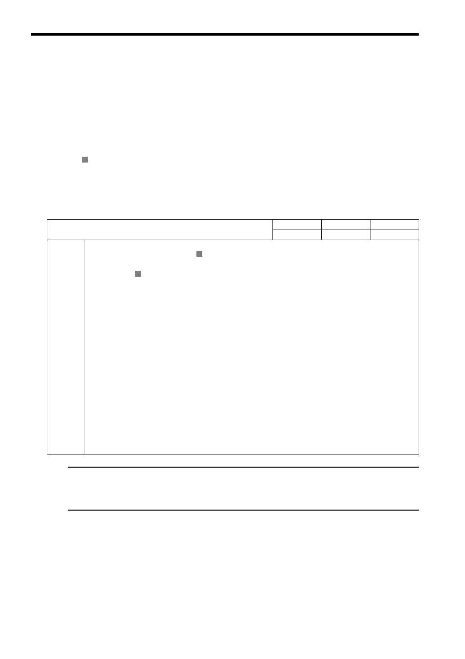
R
No. 0
Selection of Operation Modes
Setting Range
Setting Unit
Default Value
0 to 3
−
0
Description
Specify the application method of the axis.
0: Normal Operation Mode (default)
Use this setting when actually using an axis.
1: Axis Unused
No control will be performed for an axis set to this mode, and monitoring parameters will not be updated. If an axis is
changed from any other run mode to this mode, the monitoring parameters will be held at the current status except for the
RUN Status (monitoring parameter IW
00), which will be cleared to zeros.
Set any axis that is not being used to this mode (Axis Unused) to reduce the processing time.
2: Simulation Mode
In Simulation Mode, position information will be stored in the monitoring parameters even if a Servo Driver is not con-
nected.
This mode is used to virtually check the operation of the applications program.
In Simulation Mode, axis motions cannot be simulated. If a positioning command is executed, for
example, the execution of the command will enter completed status at the next scan. Use an SVR
Module to check axis motions.
3: Servo Driver Transmission Reference Mode
Servo Driver Transmission Reference Mode is used to directly control the command-response communication with the
MECHATROLINK SERVOPACK from the application.
No processing other than communication processing with the SERVOPACK will be performed in this mode. Position
control and other processing must be performed in the application.
Commands to the SERVOPACK are set in the area starting with setting parameter OW
70 or later and responses are
stored in the area starting with monitoring parameter IW
70 or later.
Refer to Appendix I Servo Driver Transmission Reference Mode for details on Servo Driver Transmis-
sion Reference Mode.
R
R