4 system configuration example – Yaskawa MP2000 Series: Built-in SVB or SVB-01 Motion Module User Manual
Page 19
1.1 SVB Module Overview and Features
1.1.4 System Configuration Example
1-3
Overview
1.1.4 System Configuration Example
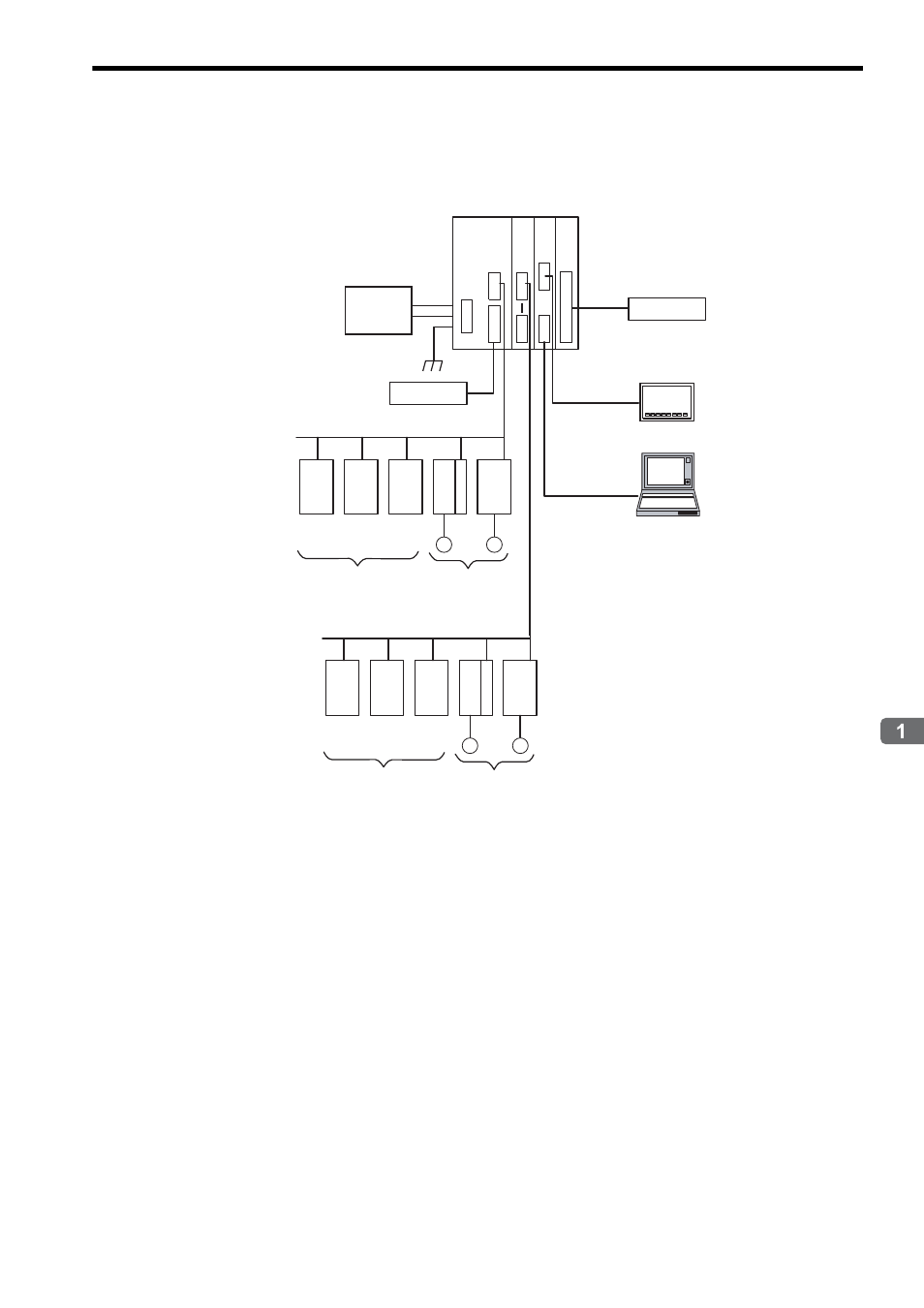
The following diagram shows a system configuration example.
Use the specified cables and connectors. Refer to 1.1.5 ( 3 ) Cables to select appropriate cables and connectors to
connect each device.
The SERVOPACK models that can be connected through MECHATROLINK-I differ from those connected through
MECHATROLINK-II. Refer to 1.1.5 Devices Connectable to MECHATROLINK to select appropriate SERVOPACK
models for the MECHATROLINK interface to be used.
If both MECHATROLINK-I (4 Mbps) compatible devices and MECHATROLINK-II (10 Mbps) compatible devices are
connected in a system, make the settings in accordance with MECHATROLINK-I specifications.
When connecting a servo to an SVB Module via MECHATROLINK, connect signals such as overtravel, homing
deceleration switch, and external latch to the servo. Refer to the relevant SERVOPACK manual for details on the
connections.
When connecting
Σ-II series SERVOPACKs (SGDH+NS100 or SGDH+NS115), do not connect a hand-held type
digital operator and SigmaWin+. If connected, alarms A.95 (command warning) and A.ED (execution not completed)
will occur for the commands sent from the SVB Module, and normal operation will be interrupted. If a digital operator
or SigmaWin+ must be connected to a
Σ-II series SERVOPACK, disconnect the SERVOPACK from the SVB Mod-
ule.
MP2300
MECHATROLINK-II
SGDS
M
IO2310
PL2900
PL2910
NS1
15
SGDH
M
MECHATROLINK-II
SGDS
M
IO2310
PL2900
PL2910
NS1
15
SGDH
M
Ethernet
RS-232C
218IF LIO-01
SVB-01
MPE720
External I/O
24-VDC
power
supply
MECHATROLINK-
compatible I/O Modules
Servos
MECHATROLINK-
compatible I/O Modules
Servos
External I/O
Control panel