2 motion setting parameter details, 1 ) run command setting – Yaskawa MP2000 Series: Built-in SVB or SVB-01 Motion Module User Manual
Page 101
4.4 MP2000 Series Machine Controller Parameter Details
4.4.2 Motion Setting Parameter Details
4-25
Motion Parameters
4.4.2 Motion Setting Parameter Details
The following tables provide details of motion setting parameters.
Refer to 4.3.2 Setting Parameter List for a list of the motion setting parameters.
Register number “OW
00” indicates the leading output register number + 00.Other register numbers listed below
indicate output register numbers in the same way. Refer to 4.1.1 Motion Parameter Register Numbers for MP2000
Series Machine Controllers for information on how to find the leading output register number.
in the following tables indicates that the item is also compatible with SVR.
in the following descriptions indicate that parameter is enabled in position control,
phase control, speed control, or torque control.
Similarly,
in the following descriptions indicate that parameter is disabled in position
control, phase control, speed control, or torque control.
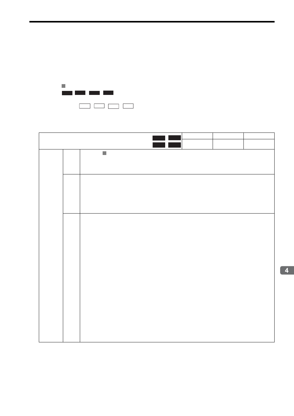
( 1 ) RUN Command Setting
R
Position
Phase
Speed
Torque
Speed
Torque
Position
Phase
OW
00
RUN Command Setting
Setting Range
Setting Unit
Default Value
−
−
0000H
Description
Bit 0
Servo ON
Sends a SERVO ON command to the SERVOPACK.
0: Servo OFF (default)
1: Servo ON
Bit 1
Machine Lock
0: Machine lock mode released (default)
1: Machine lock mode
During the machine lock mode, the Calculated Position in Machine Coordinate System (CPOS) (monitoring
parameter IL
10) will be updated but no movement will occur on the axis.
A change in the machine lock mode is valid after all pulses have been distributed. The machine lock mode can-
not be changed during speed or torque control.
Bit 4
Latch Detection Demand
0: OFF (default)
1: ON
When this bit is set to 1 (ON), the position at the moment the latch signal turns ON will be reported to the mon-
itoring parameter IL
18 “Machine Coordinate System Latch Position (LPOS).”
When the position is detected and reported, bit 2 “Latch Completed” of the monitoring parameter IW
0C
“Position Management Status” will turn ON.
To detect the position again, reset this bit to 0 (OFF) and then set to 1 (ON) again.
Use bits 0 to 3 (Latch Detection Signal Selection) of the setting parameter OW
04 (Function Setting 2) to
set the latch signal to be used.
This function is enabled only through MECHATROLINK-II in 32-byte mode because this function is imple-
mented using the servo command expanded area.
During processing, the following values will be stored in monitoring parameter IW
0A “Motion Subcom-
mand Response Code.”
Latch request: IW
0A = 25
Cancel latch request: IW
0A = 26
Do not set this bit to 1 (ON) while the motion commands “Zero Point Return,” “External Posi-
tioning,” or “Latch” are being executed. Otherwise, a warning may occur in the SERVOPACK.
With SVB-01 version 1.20 or later and built-in SVB version 2.50 or later, the subcommands
“Latch request” and “Cancel latch request” have priority over other subcommands. Care must
be taken in an application where the ON/OFF operation of the latch request is repeated
because processing for other subcommands may be suspended.
Refer to 11.4 Modal Latch Function for details of the latch function.
Position
Phase
Speed Torque
R