Yaskawa MP2000 Series: Built-in SVB or SVB-01 Motion Module User Manual
Page 147
4.4 MP2000 Series Machine Controller Parameter Details
4.4.3 Motion Monitoring Parameter Details
4-71
Motion Parameters
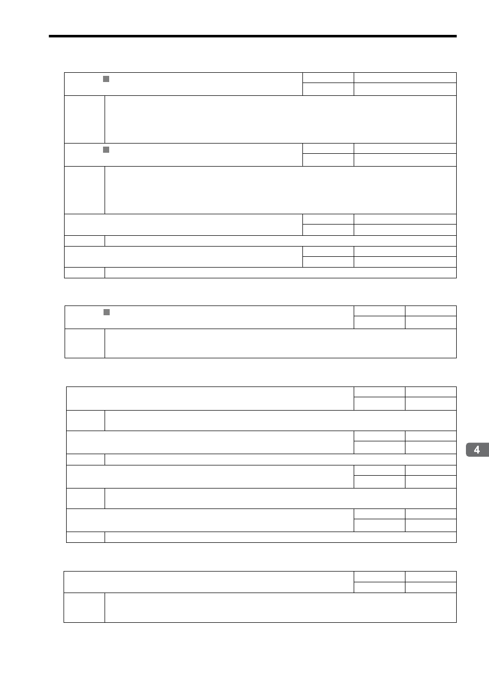
( 17 ) Additional Information
( 18 ) Absolute Infinite Length Axis Position Control Information
( 19 ) Servo Driver Transmission Reference Mode
IL
40
Feedback Speed
Range
Unit
−2
31
to 2
31
−1
Depends on speed unit.
Description
Stores the feedback speed.
The value is determined by the moving average time constant (fixed parameter 42) and unit set from the difference with
the Machine Coordinate System Feedback Position (APOS) (monitoring parameter IL
16) in each scan.
The setting unit for this parameter depends on the Speed Unit Selection (OW
03, bits 0 to 3), but
the result of applying the speed unit setting is not shown here.
IL
42
Feedback Torque/Thrust
Range
Unit
−2
31
to 2
31
−1
Depends on the Torque Unit
Description
Stores the value of the torque reference.
The Feedback Torque/Thrust is achieved using the Servo command expansion area and can be executed only with the
MECHATROLINK-II, 32-byte Mode communication method.
The setting unit for this parameter depends on the Torque Unit Selection (OW
03, bits C to F), but
the result of applying the torque unit setting is not shown here.
IW
44
Latch Completion Sequence Number
Range
Unit
0 to 32767
1 = 1 time
Description
Available only for SGDV SERVOPACKs using the MECHATROLINK-II network (32 bytes).
IW
45
Latch Completion Sequence Number
Range
Unit
0 to 32767
1 = 1 cycle
Description
Available only for SGDV SERVOPACKs using the MECHATROLINK-II network (32 bytes).
IL
56
Fixed Parameter Monitor
Range
Unit
−2
31
to 2
31
−1
−
Description
Stores the data of the specified fixed parameter number.
This parameter stores the data of the fixed parameter when the Read Fixed Parameter (FIXPRM-RD) is selected in the
Motion Subcommand (setting parameter OW
0A).
IL
5E
Encoder Position When the Power is OFF (Lower 2 words)
Range
Unit
−2
31
to 2
31
−1
pulse
Description
Stores information used for infinite length axis position control when an absolute encoder is used.
The encoder position is normally stored in 4 words.
IL
60
Encoder Position When the Power is OFF (Upper 2 words)
Range
Unit
−2
31
to 2
31
−1
pulse
Description
Same as for IL
5E.
IL
62
Pulse Position When the Power is OFF (Lower 2 words)
Range
Unit
−2
31
to 2
31
−1
pulse
Description
Stores information used for infinite length axis position control when an absolute encoder is used.
These parameters store the axis position managed by the Machine Controller in pulses in 4 words.
IL
64
Pulse Position When the Power is OFF (Upper 2 words)
Range
Unit
−2
31
to 2
31
−1
pulse
Description
Same as for IL
62.
IW
70 to IW
7E
Response Buffer for Servo Driver Transmission Reference Mode
Range
Unit
−
−
Description
This area is used for response data when MECHATROLINK Servo commands are specified directly.
• MECHATROLINK-I and MECHATROLINK-II, 17-byte Mode: Data area = IW
70 to IW
77
• MECHATROLINK-II, 32-byte Mode: Data area = IW
70 to IW
7E
R
R
R