5 inverter input data details – Yaskawa MP2000 Series: Built-in SVB or SVB-01 Motion Module User Manual
Page 409
10.4 Motion Parameter Details
10.4.5 Inverter Input Data Details
10-45
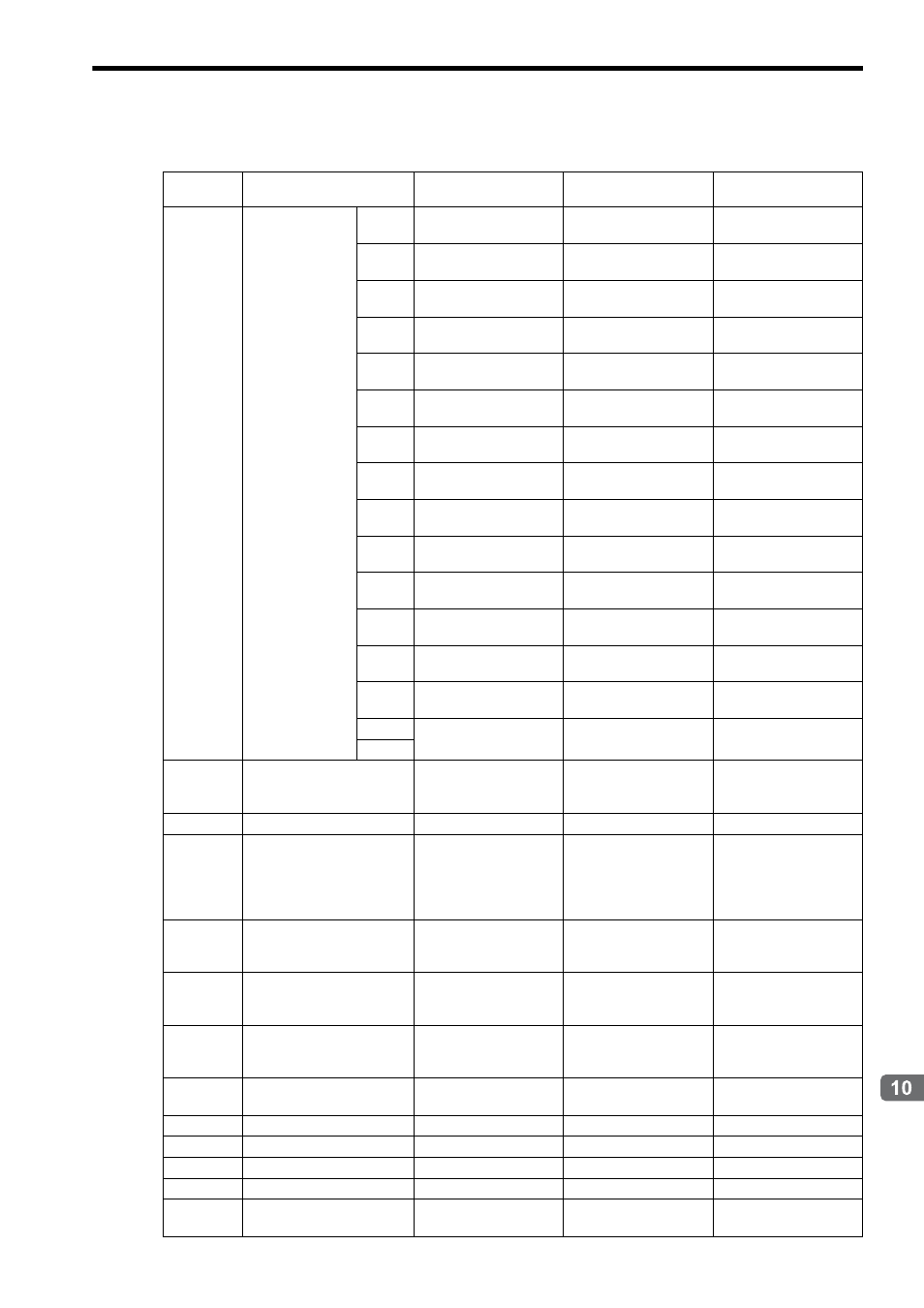
Settings for Connecting Inverters
10.4.5 Inverter Input Data Details
Register
No.
Name
Varispeed G7
Varispeed F7
VSminiV7
IW
10
Status
Bit 0
Alarm
ALM
Alarm
ALM
Alarm
ALM
Bit 1
Warning
WARNG
Warning
WARNG
Warning
WARNG
Bit 2
Command Ready
CMDRDY
Command Ready
CMDRDY
Command Ready
CMDRDY
Bit 3
Base Block
BB OFS
Base Block
BB OFS
Base Block
BB OFS
Bit 4
Power ON
PON
Power ON
PON
Power ON
PON
Bit 5
During Running
RUNX
During Running
RUNX
During Running
RUNX
Bit 6
Zero Speed
OSP
Zero Speed
OSP
Zero Speed
OSP
Bit 7
Reverse Operation
REV
Reverse Operation
REV
Reverse Operation
REV
Bit 8
During Reset
RESET
During Reset
RESET
During Reset
RESET
Bit 9
During Speed Coincident
AGREE
During Speed Coincident
AGREE
During Speed Coincident
AGREE
Bit A
Inverter Ready
INV_READY
Inverter Ready
INV_READY
Inverter Ready
INV_READY
Bit B
OPE Error
OPE
OPE Error
OPE
OPE Error
OPE
Bit C
Momentary/Power Cut
UV_R
Momentary/Power Cut
UV_R
Momentary/Power Cut
UV_R
Bit D
Remote Operation
REMOTE
Remote Operation
REMOTE
Remote Operation
REMOTE
Bit E
Reserved by the system.
Reserved by the system.
Reserved by the system.
Bit F
IW
11
Output Frequency
Unit depends on the
inverter user constant 01-
03.
Unit depends on the
inverter user constant 01-
03.
Unit depends on the
inverter user constant
n035.
IW
12
Output Current
Unit: 0.1 A or 0.01 A
Unit: 0.1 A or 0.01 A
Unit: 0.1 A or 0.01 A
IW
13
Motor Speed (Option)
Unit depends on the
inverter user constant 01-
03.
(Invalid in V/f with PG
control mode)
Unit depends on the
inverter user constant 01-
03.
(Invalid in V/f with PG
control mode)
Unit depends on the
inverter user constant
n035.
(Output Frequency in V/f
with PG control mode)
IW
14
Torque Reference (U1-09)
(Option)
Unit: 0.1%
(Invalid in V/f with PG
and V/f control mode)
Unit: 0.1%
(Invalid in V/f with PG
and V/f control mode)
Unit: 0.1%
(Invalid in V/f with PG
control mode)
IW
15
Encoder Count (Option)
Unit: pulse
(Invalid when an optional
PG is not connected.)
Unit: pulse
(Invalid when an optional
PG is not connected.)
Reserved by the system.
IW
16
Frequency Reference
(U1-01) (Option)
Unit depends on the
inverter user constant 01-
03.
Unit depends on the
inverter user constant 01-
03.
Unit depends on the
inverter user constant
n035.
IW
17
Multi-function Analog Input
A2
Unit: 0.1%
Unit: 0.1%
Unit: 0.1% (RP input)
IW
18
Main Bus Voltage
Unit: 1 V
Unit: 1 V
Unit: 1 V
IW
19
Alarm Code (Option)
Alarm Code (Option)
Alarm Code (Option)
Alarm Code (Option)
IW
1A
Alarm Code (Option)
Alarm Code (Option)
Alarm Code (Option)
Alarm Code (Option)
IW
1B
Reserved by the system
−
−
−
IW
1C
Multi-function Analog Input
A3
Unit: 0.1%
Unit: 0.1%
Reserved by the system.