3 system startup using self-configuration, 1 starting the system for first time – Yaskawa MP2000 Series: Built-in SVB or SVB-01 Motion Module User Manual
Page 48
3.3 System Startup Using Self-Configuration
3.3.1 Starting the System for First Time
3-5
Self-configuration and Created Definition Files
3.3 System Startup Using Self-Configuration
System startup time can be reduced by using self-configuration.
This section describes system startup using self-configuration, in the following three circumstances.
• Starting the system for first time
• Adding an electronic device (e.g., SERVOPACK or optional module)
• Replacing electronic devices
3.3.1 Starting the System for First Time
Use the following procedure to startup a new system.
1.
Wire and connect electronic devices.
Correctly wire and connect all electronic devices to be used.
2.
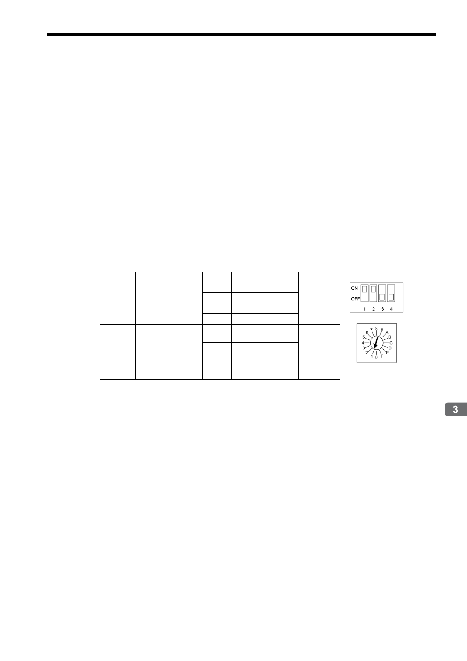
Make switch settings for MECHATROLINK slaves.
Set the MECHATROLINK communication specifications using the DIP switch and the station address on the
rotary switch on each MECHATROLINK slaves.
Example of SERVOPACK Settings (SGDS-
1
)
Refer to each slaves manual for information on the setting details.
3.
Start up MECHATROLINK slaves.
Turn ON the power to the MECHATROLINK slaves and check that the electronic devices start up normally.
If using a new Absolute Encoder, the Absolute Encoder will need to be initialized. Refer to Appendix C Initializ-
ing the Absolute Encoder for details.
The servo adjustment can be performed either in this step or after the self-configuration.
4.
Complete the settings on each optional module.
Set the required items, such as communication specifications and station address, using the switches on each
optional module mounted on the Machine Controller.
5.
Execute self-configuration.
Make sure that all the MECHATROLINK slave devices have started, and then execute self-configuration.
With self-configuration, the Machine Controller recognizes the connected MECHATROLINK slave devices and
optional modules, and assigns I/O registers. The motion parameters will automatically be set to enable the mini-
mum standard motions.
For information on how to execute self-configuration, refer to the relevant Machine Controller manual.
For the items allocated to each module, such as I/O register number, line number, motion register number,
refer to 4.1.1 Motion Parameter Register Numbers for MP2000 Series Machine Controllers.
SW1
Name
Setting
Contents
Default
Bit 1
Baud rate
OFF
4 Mbps
ON
ON
10 Mbps
Bit 2
No. of transmission
bytes
OFF
17
ON
ON
32
Bit 3
Station address
OFF
Station address =
40H+SW1
OFF
ON
Station address =
50H+SW1
Bit 4
Reserved (Reserved
by the system.)
OFF
−
OFF
SW2 (default)
SW1 (default)