Yaskawa MP2000 Series: Built-in SVB or SVB-01 Motion Module User Manual
Page 61
3.4 Self-configuration and Definition Files
3.4.2 MECHATROLINK Transmission Definition
3-18
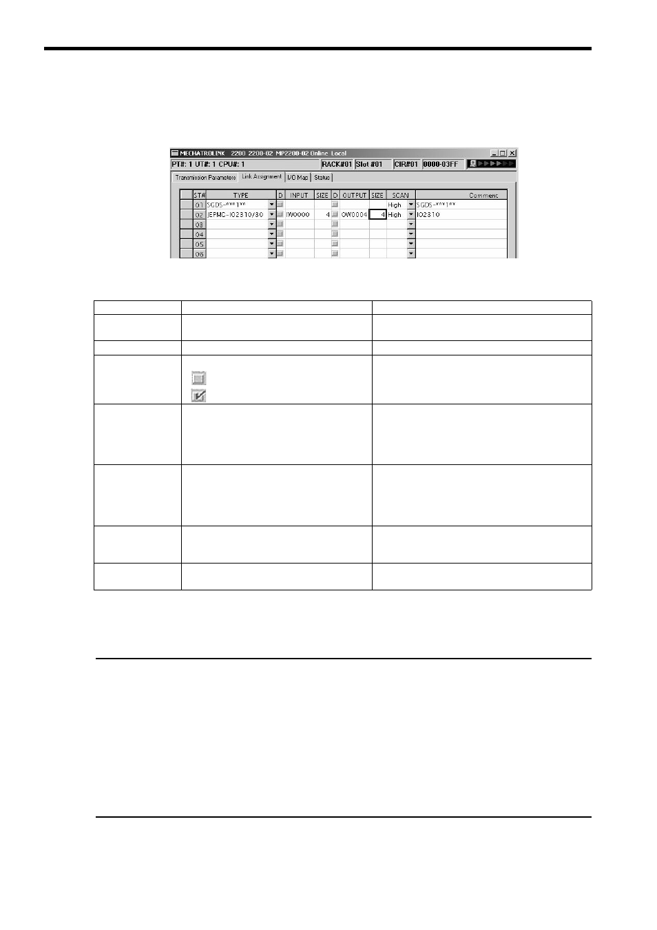
[ b ] Link Assignment Tab Page
The data of the slave devices (MECHATROLINK connected devices such as SERVOPACK, inverter, and distributed
I/O) are displayed on the Link Assignment Tab.
The items shown on the Link Assignment Tab are as follows. You can change the settings or delete the data station by
station on this tab. Always save the settings to the flash memory after changing them.
Deleting a Station Assignment
Click any cell in the row of the station to be deleted, and select Edit - Assignment Delete from the main menu.
Care must be taken when deleting a station assignment. The deletion is irreversible.
*****I/O and *****SERVO in Type
The following slave devices (I/O Modules) do not have model codes. Therefore, “*****I/O”(wild card I/O) will be displayed in
TYPE for these devices after execution of self-configuration.
• JEPMC-IO350
• JAMSC-120DAI53330
• JAMSC-120DAI73330
• JAMSC-120DAO83330
• JAMSC-120DRA83030
For a servo with customized specifications that could not be recognized by self-configuration, “*****SERVO” (wild card
servo) will be displayed in TYPE.
Select a correct device type in the Link Assignment Tab Page for the devices with *****I/O or *****SERVO displayed in
TYPE.
Item
Description
Options and Precautions on Settings
ST #
Station number
The station number set here must be the same as the
number set using rotary switches.
TYPE
Slave device connected at the station
Select the device type from the pull-down list.
D
I/O register’s enable/disable status
: Enabled
: Disabled
Click the button to switch the status.
INPUT, SIZE
The leading input register number (INPUT) and
the number of input registers in words (SIZE).
The maximum number of input registers will be
automatically set in SIZE.
When setting, be careful not to overlap the register
range among stations. The register numbers that can be
set are in the range between the leading register number
and the ending register number in the Module Configu-
ration Definition Window.
OUTPUT, SIZE
The leading output register number (OUTPUT)
and the number of input registers in words
(SIZE). The maximum number of output regis-
ters will be automatically set in SIZE.
When setting, be careful not to overlap the register
range among stations. The register numbers that can be
set are in the range between the leading register number
and the ending register number in the Module Configu-
ration Definition Window.
SCAN
Scan type used for synchronization with CPU.
High: High-speed scan
Low: Low-speed scan
Select either High or Low. When TYPE is set to a SER-
VOPACK, fixed to High.
Comment
(Station name)
−
Enter a comment of up to 32 characters for each station.