A-31, 1 ) fixed parameters, 2 ) stepper parameters – Yaskawa MP2000 Series: Built-in SVB or SVB-01 Motion Module User Manual
Page 520
Appendix G Settings when Connecting MECHATROLINK-II Compatible Stepping Motor Drivers
G.8 Writing and Changing Parameters During Self-configuration
A-31
Appendices
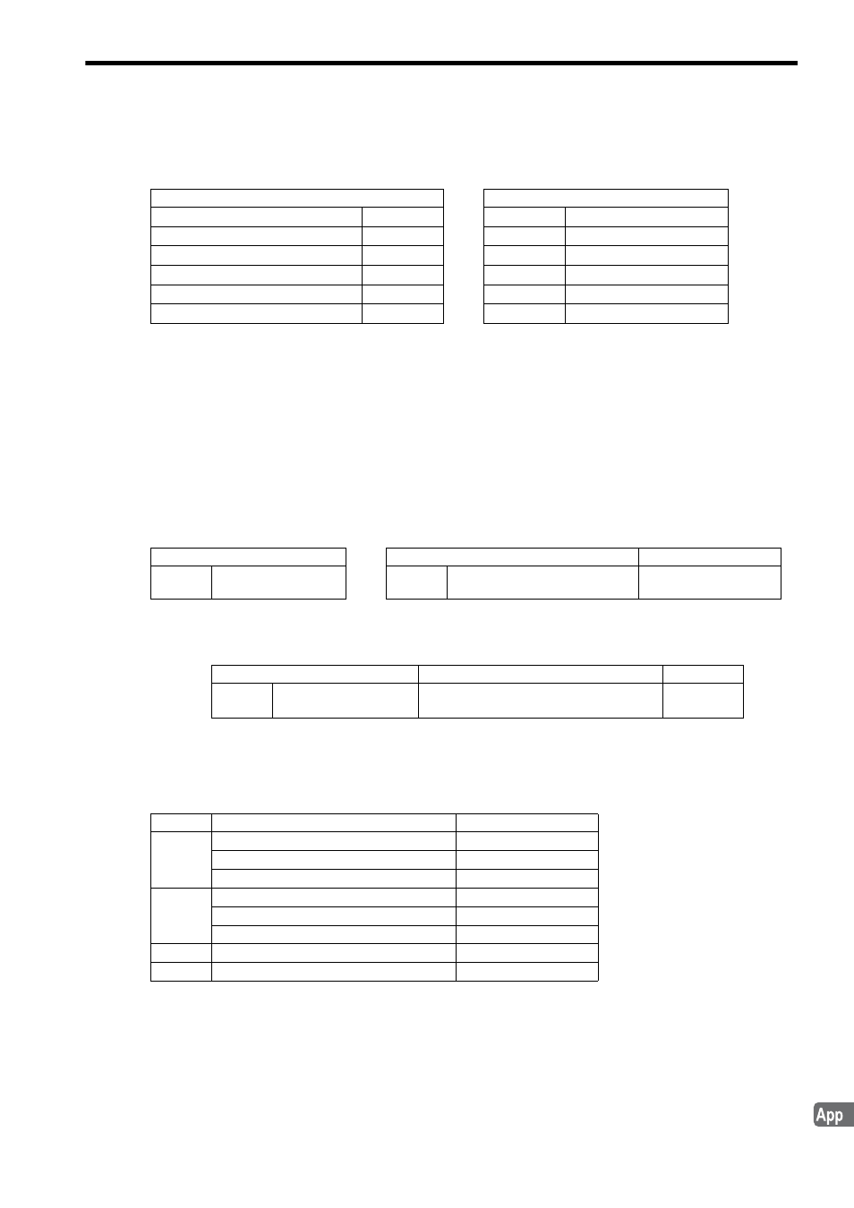
( 4 ) Parameters Updated During Self-configuration (Machine Controller to Stepper)
In any communication mode, regardless of the setting of fixed parameter No. 1, bit 10
The above processing will not be implemented for an axis that has been already defined.
G.8
Writing and Changing Parameters During Self-configuration
When a M-II Stepper is recognized as a slave, the data will be written into the Machine Controller fixed parameters,
and the settings of the stepper parameters will be changed accordingly as described below.
( 1 ) Fixed Parameters
The setting of the Basic Resolution Parameter Options bit of the stepper parameter Parameter Switch (0000h, bit 1) will
be read out. When set to Use Standard Parameter, the value of the stepper parameter Basic Resolution (0007h) will be
written into the Machine Controller fixed parameter No. 36: Encoder Resolution.
Additionally, the setting of the User Constants Self-writing Function bit of the fixed parameter Function Selection Flag
1 (No.1, bit 10) will be changed to 1 (disabled).
( 2 ) Stepper Parameters
The settings of the following parameters will be changed. Where the definition has already been made, it will stay
unchanged.
Machine Controller/Setting Parameter
M-II Stepper/Parameter
P-OT
Invalid
→
No.1, bit 2
N-OT
Invalid
→
No.1, bit 3
Software Limit by Stepper (Positive)
Invalid
→
No.2, bit 6
Software Limit by Stepper (Negative)
Invalid
→
No.2, bit 7
Electronic Gear (Numerator)
1
→
No.5
Electronic Gear (Denominator)
1
→
No.6
Stepper/Parameter
Machine Controller/Fixed Parameter
Remarks
No.7
Basic Resolution
→
No.36
Number of Pulses per Motor Rota-
tion
Unit conversion not
required
Machine Controller/Fixed Parameter
Details
Value
→
No.1
Function Selection Flag
1
Bit 10: User Constant Self-writing Function
1 (disabled)
No.
Name
Setting
1
Memory Switch 1
Bit 2: P-OT Mask
1: P-OT signal disabled
Bit 3: N-OT Mask
1: N-OT signal disabled
2
Memory Switch 2
Bit 6: Positive Software Limit Check
0: No check
Bit 7: Negative Software Limit Check
0: No check
3
Electronic Gear (Numerator)
1
4
Electronic Gear (Denominator)
1